
Quick Answer
Designing a beam correctly is critical for ensuring structural safety, efficiency, and longevity in any building project. A well-designed beam resists loads effectively without excessive deflection or failure, balancing structural strength, material economy, and compliance with codes. To achieve this, engineers must consider load type, span length, support conditions, cross-sectional properties, and material selection. The use of design aids like moment and shear diagrams, combined with real-world knowledge, ensures optimal results.
Key steps include defining all load cases (dead, live, wind, seismic), selecting the correct beam type (simply supported, cantilever, continuous), determining the bending moment and shear forces, choosing the most efficient cross-section (like I-beams for steel or rectangular for concrete), and ensuring deflection limits are not exceeded.
- Define accurate load types and magnitudes
- Choose the correct beam type based on support and application
- Use moment and shear diagrams to guide reinforcement or section design
- Select appropriate materials and cross-section for strength and economy
- Check deflection, shear, and bearing capacities per building codes
Designing a beam is a complex but manageable task when guided by structural fundamentals, practical tools, and expert judgment. Let’s explore it further below.
Understand the Type of Load on the Beam
The first and most critical step in beam design is identifying the types of loads the beam must carry. These typically include:
- Dead loads: Permanent loads like the weight of the beam itself, floor slabs, roofing materials, and fixed equipment.
- Live loads: Temporary or movable loads such as people, furniture, or vehicles.
- Environmental loads: Wind, seismic, thermal expansion, and snow loads, depending on location.
Each of these load types influences how the beam will bend, shear, and deflect. For example, live loads vary in intensity and placement, while dead loads are more uniform and predictable. Wind and seismic loads introduce lateral forces that can cause torsion or vibration.
Real-World Example
In multi-story residential buildings, beams in living areas may primarily resist live loads, while roof beams in cold climates must be designed for snow and wind loads. For critical structures like hospitals or data centers, higher safety factors and load combinations are required.
Properly categorizing and quantifying these loads according to ASCE 7 (U.S.) or Eurocode EN 1991 (EU) ensures the beam is neither over- nor under-designed.
Choose the Right Support Type
The beam’s support condition directly influences how forces are transferred and resisted. The three main support types are:
- Simply supported: Free to rotate at supports; no moment resistance.
- Fixed: Rigidly held at ends; resists both vertical forces and bending moments.
- Cantilever: Supported at one end only, with overhanging extension.
Each configuration changes how moments and shear forces are distributed. For instance, a fixed beam experiences less deflection and lower maximum moments than a simply supported beam of the same span and load.
Practical Tip
For residential flooring, simply supported beams are common due to ease of installation. For bridges or overhangs, cantilever beams are often used to minimize support interference.
Selecting the right support system improves performance, reduces material usage, and simplifies construction.
Determine Span and Effective Length
Span refers to the distance between two supports, while effective length takes into account how the beam bends and interacts with its environment. Effective length may differ from clear span due to:
- Beam end fixity (fixed ends reduce effective length)
- Load distribution (uniform vs point loads)
- Lateral bracing (reduces buckling risk)
Longer spans increase bending moments and deflections, requiring larger or stiffer sections. Conversely, short spans can be uneconomical if overdesigned.
Engineering Note
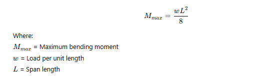
A simply supported beam with a 6-meter span under a uniformly distributed load will have its maximum bending moment at midspan. Using standard formulas, engineers calculate:
Accurate span measurement and realistic estimation of effective length are key for performance and code compliance.
Select the Beam Cross-Section Wisely
The cross-sectional shape of a beam influences its strength, stiffness, and material economy. Common choices include:
| Beam Type | Material | Best For |
|---|---|---|
| I-beam (W-shape) | Steel | Long spans, high strength |
| Rectangular | Concrete | Residential, commercial floors |
| T-beam | Concrete | Integrated floor-beam systems |
| Box section | Steel | Torsional resistance |
| Glulam | Wood | Sustainable, aesthetic designs |
Comparative Insight
I-beams maximize the moment of inertia with minimal material, making them ideal for bending resistance. Concrete beams are often rectangular for simplicity but may incorporate steel rebar to resist tensile forces.
For reinforced concrete, the width-to-depth ratio, cover thickness, and placement of reinforcement must all be optimized to meet structural and code requirements.
Calculate Bending Moments and Shear Forces
Bending moments and shear forces determine the internal stresses a beam will experience under various loading conditions. Accurate calculation of these values is essential for safe and cost-effective design.
Bending Moment (M)
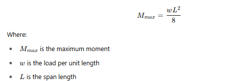
The bending moment is highest at points where the load effect is greatest. For a simply supported beam under a uniform load:
For point loads or multiple spans, moment distribution methods like moment-area theorems, conjugate beam method, or software-based tools (STAAD, SAP2000) are used.
Shear Force (V)
Shear force is highest at supports. For uniform loading:

Real-World Application
In a parking garage beam supporting car loads, ignoring peak shear near supports could lead to brittle shear failure. Shear stirrups or web reinforcement is often used in concrete beams to address this.
Engineers also develop shear and moment diagrams to visualize internal forces along the beam’s length. These guide placement and quantity of reinforcement.
Check Deflection Limits
While strength is essential, excessive deflection can lead to serviceability issues like cracked finishes, bouncing floors, or misaligned doors. Deflection should not exceed code-specified limits.
Common Limits
| Beam Use Case | Maximum Deflection |
|---|---|
| Floor beams (residential) | L/360 |
| Roof beams (non-brittle ceiling) | L/240 |
| Beams supporting brittle finishes | L/480 |
Where LLL is the beam’s span in inches or mm.
Calculation Example
For a 6-meter span residential floor beam:
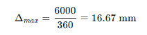
If the calculated deflection exceeds this, a deeper section or stiffer material is required.
Deflection checks are vital for user comfort, aesthetics, and long-term performance.
Design for Shear and Torsion
In addition to bending, beams may experience shear and torsional forces, especially in irregular load cases or framing systems.
Shear Design
- Shear is resisted by concrete and stirrups in RC beams.
- For steel, web thickness and stiffeners play a key role.
- Always check at d-distance from supports (effective depth).
Torsion Design
- Beams in curved frames or those carrying eccentric loads can twist.
- Closed stirrups or torsional reinforcement is required in concrete beams.
- Hollow or box sections resist torsion more effectively than I-beams.
Industry Insight
Balconies, curved slabs, or beams framing into staircases often require torsional checks. Ignoring these forces can lead to diagonal cracking or even twisting failure.
Use torsional design criteria from ACI 318 or Eurocode 2, depending on jurisdiction.
Optimize Reinforcement Layout
In reinforced concrete beams, steel reinforcement placement determines how well the beam resists tension, shear, and torsion.
Key Guidelines
- Place tension reinforcement at the bottom in simply supported beams.
- Use compression reinforcement for ductility and crack control.
- Provide adequate cover to protect against corrosion.
- Anchor bars beyond tension zones with proper development length.
- Use stirrups at closer spacing near supports for shear.
Reinforcement Ratios
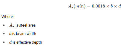
Code-mandated reinforcement ratios ensure adequate ductility and strength. For example, ACI requires:
- Minimum tensile steel area:
Practical Tip
Always use bar bending schedules and detail drawings to guide site execution. Mistakes in anchorage or spacing are among the top causes of failure.
Consider Beam Stability and Lateral-Torsional Buckling
While internal strength is critical, overall stability of the beam, especially against lateral-torsional buckling (LTB), is equally important—particularly for steel and timber beams with long, slender spans.
What is Lateral-Torsional Buckling?
LTB occurs when a beam under bending deflects sideways and twists simultaneously, typically before reaching its full bending capacity. It’s most common in unbraced steel beams under compression at the top flange.
How to Prevent LTB
- Provide lateral bracing at intervals to restrict side movement.
- Use beams with wider flanges or greater torsional stiffness (e.g., box sections).
- Reduce unbraced length by intermediate supports or floor connections.
- Apply design equations or FEM software to determine buckling resistance.
Engineering Case
In steel warehouses, roof beams with long spans and minimal bracing are susceptible to LTB. Adding purlins or cross bracing dramatically increases stability.
Designers should refer to AISC (U.S.) or Eurocode 3 (EU) clauses to calculate the critical buckling moment and design accordingly.
Use Efficient Beam Materials
Material choice affects cost, constructability, weight, and performance. The three main types of beam materials are:
1. Steel
- High strength-to-weight ratio
- Prefabricated shapes (W, I, box)
- Ideal for long spans and heavy loads
2. Reinforced Concrete
- Combines strength of concrete (compression) and steel (tension)
- Durable and fire-resistant
- Best for moderate spans and building integration
3. Timber
- Sustainable and lightweight
- Aesthetically appealing for interiors
- Suitable for light residential or hybrid buildings
| Material | Max Span Range | Cost Efficiency | Best Use |
|---|---|---|---|
| Steel | 10–40 m | High for long spans | Bridges, warehouses |
| Concrete | 3–15 m | Moderate | Homes, offices |
| Timber (glulam) | 3–12 m | Moderate–High | Halls, homes, churches |
Hybrid Systems
Composite beams (steel + concrete) combine advantages: steel for tension, concrete for compression, minimizing weight and cost.
Material selection should match structural demands, availability, fire resistance, and budget constraints.
Account for Load Combinations and Safety Factors
Beam design must account for different loading combinations and include safety factors to ensure reliability under various scenarios.
Common Load Combinations (U.S. per ASCE 7-16)
- 1.4D (Dead Load only)
- 1.2D + 1.6L (Dead + Live)
- 1.2D + 1.6W + 0.5L (Dead + Wind + Live)
- 1.2D + 1.0E + 0.5L (Dead + Earthquake + Live)
Partial Safety Factors (Eurocode EN 1990)
- γG=1.35\gamma_G = 1.35γG=1.35 (Dead Load)
- γQ=1.5\gamma_Q = 1.5γQ=1.5 (Live Load)
- γW=1.5\gamma_W = 1.5γW=1.5 (Wind)
These ensure structures withstand unexpected loads or conditions.
Software Tip
Modern software (ETABS, SAP2000, Robot) automates combination generation and factor application. Still, understanding the logic is critical for verification.
Using conservative yet rational combinations avoids overdesign and reduces unnecessary material use.
Incorporate Serviceability Considerations
Serviceability governs the user experience and functionality of structures. Even if a beam is strong enough, it must perform without issues like:
- Excessive vibration
- Cracks or visible sagging
- Finish damage or floor misalignment
Control Measures
- Deflection control (covered earlier)
- Vibration limits, especially in lightweight floors or gymnasiums
- Crack width limitation, especially in exposed concrete
- Cambering steel beams to offset long-term deflection
Real-World Issue
In offices with sensitive equipment, floor vibrations from walking or movement can affect operation. Beam frequency and damping must be checked and adjusted as needed.
Serviceability design ensures comfort, aesthetics, and long-term satisfaction—often overlooked but essential.
Expert Tips to Remember
- Design for Realistic Loads, Not Just Maximums
Overdesigning leads to material waste. Use probabilistic load combinations to balance safety with cost. - Prioritize Beam Depth Over Width for Stiffness
Moment of inertia increases with the cube of depth, making deeper beams more efficient for limiting deflection. - Never Ignore Shear and Torsion Near Supports
Most failures occur at or near supports—ensure proper detailing and reinforcement anchorage. - Use Moment and Shear Diagrams as Your Guide
They help identify critical regions for reinforcement, bracing, or cross-section adjustments. - Always Check Against Local and National Codes
Whether ACI, Eurocode, or IS codes, compliance ensures safety, legality, and approval during inspections.
FAQs
1. What is the most efficient shape for a beam?
I-beams or W-sections are typically the most efficient for resisting bending due to their high moment of inertia and material concentration at flanges.
2. How do I choose between steel and concrete beams?
Use steel for long spans and speed of erection; concrete is better for cost-effectiveness in mid-rise or integrated structures.
3. What is the minimum reinforcement in a concrete beam?
Codes like ACI require at least 0.0018 × b × d of tensile reinforcement to prevent brittle failure.
4. Can a beam fail without visible cracks?
Yes, especially in shear or torsion. That’s why internal stresses and safety factors are vital in design.
5. What causes excessive beam deflection?
Undersized sections, long spans, high loads, or inadequate material stiffness (low E-modulus) can all contribute.
6. How often should I place lateral bracing in steel beams?
This depends on span length and load, but placing bracing every 4–6 feet is common for lightly loaded beams.
7. Are cantilever beams more prone to failure?
They experience higher moments at the fixed support and can twist or deflect significantly if not properly designed.
8. Why is cover thickness important in concrete beams?
It protects reinforcement from corrosion, ensures fire resistance, and affects development length.
9. What software is best for beam design?
STAAD.Pro, ETABS, and SAP2000 are leading tools for structural engineers, offering load simulation and code compliance.
10. Can timber beams be used in commercial buildings?
Yes—especially engineered wood like glulam or CLT, which meets strength and fire standards in many jurisdictions.
Conclusion
Designing a beam is a multidimensional task that goes beyond simple strength calculations. It involves understanding load behavior, selecting the right material and support type, and ensuring compliance with both strength and serviceability criteria. Whether for residential homes or complex commercial structures, applying a systematic approach to beam design ensures structural integrity, efficiency, and user comfort. From bending moments to vibration control, each detail contributes to a safe and lasting result.
Key Takeaways
- Beam design must address bending, shear, torsion, and deflection for full safety and usability.
- Load types and combinations determine the size and reinforcement needs.
- Choosing the right cross-section and support type improves performance and material use.
- Lateral-torsional buckling must be addressed, especially in long steel beams.
- Serviceability factors like vibration and crack control are as important as strength.
