
Quick Answer
Combined footing design is essential when two or more columns are so close together that their footings overlap or when a column is near a property line, restricting space. This foundation type distributes loads uniformly to avoid differential settlement and maintain structural integrity. It’s commonly used in residential, commercial, and industrial construction.
Design involves determining the size, shape (rectangular or trapezoidal), reinforcement layout, and checking for shear and moment capacities. Factors like column loads, soil bearing capacity, and spacing between columns play a critical role. Structural engineers often rely on simplified assumptions or software tools, but a hand calculation approach rooted in equilibrium principles remains fundamental.
- Used when individual footings would overlap or be impractical
- Two main types: rectangular and trapezoidal combined footings
- Key parameters: column loads, spacing, soil bearing capacity
- Reinforcement must resist bending moments and shear forces
- Examples include shared footings between property lines or clustered columns
Let’s explore it further below.
What Is a Combined Footing and When Is It Used?
A combined footing is a type of shallow foundation that supports more than one column when their individual footings would overlap or be too close to each other. It serves to evenly distribute loads from adjacent columns onto the soil when spacing or structural constraints prevent isolated footings.
Common Scenarios Where Combined Footings Are Needed:
- Property Line Constraints: When a column is close to the boundary, placing an isolated footing symmetrically is not possible.
- Closely Spaced Columns: If two columns are close enough that their isolated footings would merge, a combined footing offers structural continuity.
- Unequal Column Loads: When column loads vary significantly, a trapezoidal footing ensures uniform soil pressure distribution.
- Structural Uniformity: In industrial buildings or facilities with machines needing equal vibration support, combined footings improve load transfer.
Real-World Example
Consider two columns, one carrying 1000 kN and the other 1500 kN, spaced 3.5 m apart. If isolated footings were placed beneath each, the overlapping region would make construction difficult and inefficient. A combined rectangular or trapezoidal footing allows for a single foundation element, simplifying reinforcement and ensuring even settlement.
Combined footings are particularly effective in poor soil conditions where larger foundation areas are required to reduce bearing pressure.
Types of Combined Footings and Their Applications
The geometry of a combined footing depends on the loading and spacing of the columns. The two primary types are:
1. Rectangular Combined Footing
- Used when: Column loads are nearly equal and symmetrically spaced.
- Layout: Rectangular slab covering both columns.
- Design simplicity: Easier to analyze and construct.
- Soil pressure distribution: Generally uniform.
- Example: Two 1200 kN columns spaced 2 m apart on uniform soil.
2. Trapezoidal Combined Footing
- Used when: Column loads are unequal or column spacing is asymmetrical.
- Layout: Wider at the end of the heavier column, forming a trapezoid.
- Soil pressure: Still aimed to be uniform under centroid.
- More complex design: Requires centroid calculations to align with resultant force.
| Feature | Rectangular Footing | Trapezoidal Footing |
|---|---|---|
| Load symmetry required | Yes | No |
| Shape | Rectangle | Trapezoid |
| Reinforcement complexity | Moderate | Higher |
| Soil pressure distribution | Uniform | Uniform (via geometry) |
| Preferred for equal loads | ✅ | ❌ |
When to Choose Which?
If you’re dealing with columns of nearly equal load and spacing, a rectangular footing is more economical. For columns with significant load disparity, trapezoidal footings allow proper pressure balancing.
Step-by-Step Design Process for Combined Footings
A methodical approach ensures that the combined footing performs as intended under all loading conditions. Here’s a generalized step-by-step guide:
1. Gather Input Data
- Column loads (P₁, P₂)
- Column dimensions
- Center-to-center spacing
- Soil bearing capacity (SBC)
- Minimum cover and reinforcement specs
2. Determine Required Footing Area
Use:
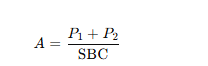
Add safety margin based on code (typically 1.5–2.0× factor).
3. Footing Shape and Size
- Choose rectangular if loads are similar; otherwise, trapezoidal.
- Determine total length (L) and width (B) to match area.
- Locate centroid of footing such that the resultant force aligns.
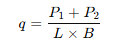
4. Load Distribution and Soil Pressure
- Compute eccentricity (e) between column resultant and footing centroid.
- Calculate uniform or linear varying pressure under footing:
5. Shear and Moment Analysis
- Compute bending moment at critical sections (under each column).
- Check for one-way (beam-like) and two-way (punching) shear.
6. Reinforcement Design
- Use flexural formulas to determine required steel.
- Ensure minimum bar spacing and cover as per local codes (e.g., ACI, Eurocode, IS 456).
7. Structural Detailing
- Longitudinal bars under tension zones.
- Transverse bars for shear and crack control.
- Proper development length and anchorage.
Common Design Mistakes and How to Avoid Them
Combined footings can seem straightforward, but several pitfalls can compromise their integrity. Here’s how to steer clear:
1. Ignoring Load Eccentricity
Misalignment between the resultant load and the centroid of the footing leads to uneven soil pressure and differential settlement.
Fix: Always balance the footing centroid with the resultant load using geometry or soil pressure formulas.
2. Underestimating Soil Bearing Capacity
Relying on general values instead of site-specific geotechnical reports can cause undersized footings.
Fix: Conduct or request soil investigations to determine accurate SBC.
3. Improper Reinforcement Layout
Failing to place reinforcement exactly where tensile forces develop can lead to cracking or early failure.
Fix: Use moment and shear diagrams to guide bar placement and lap splices.
4. Overlooking Construction Tolerances
Too narrow a margin between the footing and the property line or other columns can lead to formwork and concreting issues.
Fix: Add at least 100–150 mm clearance from edges and obstacles.
5. Neglecting Differential Settlement Risk
Columns with vastly different loads or soil conditions beneath may settle unevenly.
Fix: Use thicker footing or flexible connections in the superstructure to accommodate some movement.
Real-World Example: Rectangular Combined Footing Design
Let’s walk through a practical rectangular combined footing design using a simplified hand calculation method. This example assumes common values and steps used in both US and EU structural engineering practices.
Given:
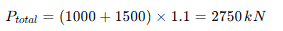
- Column 1 (P₁) = 1000 kN
- Column 2 (P₂) = 1500 kN
- Spacing between columns (center to center) = 3.6 m
- Allowable soil bearing capacity (q_allow) = 200 kN/m²
- Concrete grade = C25/30 or 25 MPa
- Reinforcement yield strength = 500 MPa
Step 1: Calculate Total Load
Add a 10% increase for footing self-weight:
Step 2: Required Area

Step 3: Choose Dimensions
Assume footing width = 2.5 m
Then:
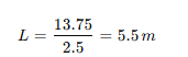
So, use footing size = 5.5 m × 2.5 m
Step 4: Position Columns
Let’s place Column 1 at 1.5 m from the left edge, Column 2 at 1.5 m + 3.6 m = 5.1 m
Centroid of loads =
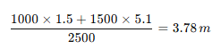
To balance, place footing centroid also at 3.78 m from Column 1. So, shift footing accordingly (edge offset: 3.78 m – 2.75 m = 1.03 m)
Step 5: Soil Pressure
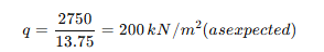
Step 6: Moment Calculation
Max moment occurs under columns. Use simplified beam theory (WL/8 for symmetric loads or manual statics for asymmetry).
Say M_max ≈ 300 kNm (approx, for learning).
Required depth using:
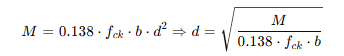
Assume f_ck = 25 MPa, b = 2500 mm:
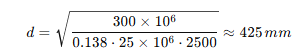
Use effective depth = 450 mm, total depth = 500 mm (including cover and bar dia)
Step 7: Reinforcement
Use:
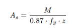
Assume lever arm z = 0.9d = 405 mm, f_y = 500 MPa:
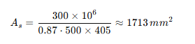
Use 5 bars of 20 mm dia:

This satisfies flexural demand.
Trapezoidal Footing Design Example with Unequal Loads
When the column loads vary significantly, a trapezoidal combined footing ensures uniform pressure by offsetting the geometry.
Given:
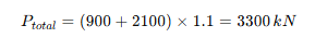
- Column 1 (P₁) = 900 kN
- Column 2 (P₂) = 2100 kN
- Center-to-center spacing = 4.2 m
- Allowable soil pressure = 180 kN/m²
- Same material strengths as before
Step 1: Total Load with 10% for footing weight
Step 2: Required Area
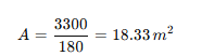
Assume total length = 5.5 m
Let widths be B₁ (narrow end), B₂ (wide end)
Step 3: Solve for B₁ and B₂
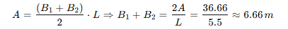
Assume B₁ = 2.5 m → then B₂ = 6.66 – 2.5 = 4.16 m
So trapezoidal footing dimensions:
- B₁ = 2.5 m
- B₂ = 4.16 m
- L = 5.5 m
Step 4: Centroid Check
Position centroid of trapezoid to match resultant load centroid. Use centroid formula for trapezoid:
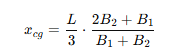
Plug in values to verify and shift geometry as needed.
Step 5: Reinforcement Design
Calculate bending moments under both columns and provide reinforcement in both directions. The trapezoidal geometry makes reinforcement detailing more complex but ensures more accurate pressure control under unequal loading.
Code Compliance in US and EU for Combined Footings
Designing combined footings requires compliance with local building codes. In the US and EU, the main references are:
ACI 318 (US)
- Minimum footing depth: per frost line, typically 12–18 inches
- Flexural design: factored loads (ASD/LRFD), moment & shear resistance
- Soil pressure limits: as per geotech report + load factors
Eurocode 7 and Eurocode 2 (EU)
- Partial safety factors: for actions (γ_F) and materials (γ_M)
- Serviceability: check for settlements
- Ultimate limit state (ULS): bearing resistance, punching shear
Key Compliance Areas
| Checkpoint | ACI 318 (US) | Eurocode (EU) |
|---|---|---|
| Load factor combo | LRFD / ASD | EN 1990 partial safety factors |
| Shear check | One-way and punching | Same, with different limits |
| Reinforcement cover | Typically 50 mm (2 in) | 25–40 mm depending on exposure |
| Frost protection | Based on regional frost depth | National annex requirements |
Always consult local regulations or the project’s geotechnical report for precise criteria.
ChatGPT said:
Reinforcement Detailing for Combined Footings
Reinforcement detailing is critical to the performance of combined footings. It ensures that the footing can safely transfer loads to the ground while resisting bending, shear, and cracking over time. Poor detailing can lead to premature structural failures, especially in areas with seismic activity or heavy dynamic loads.
Longitudinal Reinforcement (Main Bars)
- Location: Bottom face of the footing slab
- Purpose: Resist bending moments caused by column loads
- Direction: Parallel to the line joining the columns
- Spacing: Typically 150–300 mm c/c, depending on bar diameter and design moment
Example:
For a rectangular footing, provide 6 T20 bars spaced at 250 mm c/c under the column line.
Transverse Reinforcement
- Location: Also at the bottom, perpendicular to the column line
- Purpose: Control cracking, resist secondary moments, and distribute load
- Often required in: Trapezoidal footings with asymmetric pressure
Shear Reinforcement (if required)
- Types: Stirrups or bent-up bars
- Use when: One-way shear or punching shear exceeds concrete capacity
- Typically placed: Around column base, especially for columns with high loads
Cover Requirements
- ACI 318: 75 mm (3 in) for concrete cast against soil
- Eurocode 2: 40–50 mm minimum, depending on exposure class
Anchorage and Development Length
Bars must be fully developed to resist the design forces.
- Standard rule: Development length = 40–60 × bar diameter
- Use hooks or bends: To reduce development length if space is limited
Curtailment and Laps
- Main bars may be curtailed (cut off) if not required throughout
- Overlap lengths must meet code standards:
- 40 × bar diameter (tension zone, normal conditions)
- Increased if in poor bond conditions or high-stress zones
Good Detailing Practices
| Detailing Element | Best Practice |
|---|---|
| Main bars | Place near bottom, extend full length |
| Distribution bars | At 90° to main bars, extend edge to edge |
| Shear reinforcement | Add stirrups near heavy columns |
| Lap splicing | Offset in alternate bars to avoid weak zones |
| Corner anchorage | Always bend bars or use anchor hooks |
Use clear and labeled reinforcement drawings with:
- Bar schedules
- Cover dimensions
- Clearances from edge
- Notes on development lengths and laps
Software Tools for Combined Footing Design
Although manual design provides fundamental understanding, modern software can streamline the process and reduce errors—especially for complex or large-scale projects.
Popular Software Options
| Software | Features | Use Case |
|---|---|---|
| ETABS | Integrated footing design, load tracing | Building-scale structural analysis |
| SAFE | Specialized in slab and foundation design | Flat slabs, combined and mat footings |
| STAAD Foundation | Automatic design per global codes (ACI, IS, Eurocode) | Civil & industrial footings |
| PROKON | Reinforced concrete and geotechnical modules | Footing sizing, reinforcement optimization |
| Robot Structural | Finite element + code-based foundation design | Complex soil-structure interaction models |
Benefits of Using Software
- Rapid analysis with multiple load combinations
- Integrated code checks
- Graphical layout of reinforcement
- Reports for documentation and audit
Limitations
- Often requires license or subscription
- Needs experienced user to interpret results correctly
- Garbage in = garbage out — always verify inputs
When to Use
- For high-rise buildings or industrial settings
- When dealing with multiple footings in proximity
- When time or budget constraints make manual calc impractical
Cost Considerations in Combined Footing Construction
Combined footings are often cost-effective compared to isolated footings in tight spaces, but they require proper planning to avoid unexpected costs.
Major Cost Drivers
- Excavation Volume
- Larger combined footings mean wider and deeper trenches.
- In urban areas, this may require special shoring or excavation methods.
- Concrete Volume
- Higher material cost, especially for deeper or thicker slabs.
- Trapezoidal footings often need more concrete than rectangular ones.
- Steel Reinforcement
- Quantity increases with bending moment and shear requirements.
- Higher yield strength steel may reduce volume but increase cost per ton.
- Labor and Time
- Complex geometry or reinforcement layouts take more time to install.
- Errors in layout lead to rework or structural issues, increasing labor cost.
- Formwork and Materials
- Trapezoidal shapes or angled edges need custom formwork.
- Good planning can minimize reuse waste and save cost.
Approximate Unit Cost Comparison (USD)
| Type | Excavation ($/m³) | Concrete ($/m³) | Rebar ($/kg) |
|---|---|---|---|
| Rectangular footing | $25–35 | $130–160 | $1.00–1.40 |
| Trapezoidal footing | $30–40 | $140–170 | $1.20–1.60 |
Total installed cost can range from $200 to $400 per m², depending on region and design complexity.
Value Engineering Tips
- Use locally available materials to save transport costs
- Opt for higher-strength concrete if it reduces footing size
- Balance excavation vs. concrete cost (deeper ≠ always better)
- Reuse formwork where possible
Soil and Geotechnical Factors Impacting Design
The performance of any footing depends largely on the soil it rests upon. Understanding geotechnical characteristics is essential for safe and efficient footing design.
Key Geotechnical Parameters
- Allowable Bearing Capacity (q_allow): Maximum safe pressure on soil
- Soil Type: Clay, silt, sand, gravel—each behaves differently
- Water Table Depth: High water tables reduce effective bearing capacity
- Settlement Characteristics: Elastic vs. plastic deformation
- Soil Modulus (E_s): Affects footing deflection and stiffness
Common Soil Conditions
| Soil Type | Bearing Capacity (kN/m²) | Notes |
|---|---|---|
| Dense Sand | 200–400 | Good for shallow footings |
| Medium Clay | 100–200 | Risk of long-term settlement |
| Soft Clay | <100 | Often requires deep footings |
| Gravel | 300–600 | Excellent drainage |
Recommendations
- Always conduct a geotechnical investigation
- Use a safety factor (typically 2.5–3.0) when applying SBC
- Avoid designing on fill material unless tested for compaction
- Consider soil improvement (e.g., compaction, grouting) if SBC is too low
FAQs
What is a combined footing in civil engineering?
A combined footing supports two or more columns using a single foundation slab, typically when columns are too close for individual footings or near property lines. It helps distribute loads evenly to the soil, ensuring stability.
When is a combined footing preferred over isolated footings?
Combined footings are used when:
- Columns are closely spaced
- One column is near a property boundary
- Loads are significantly unequal
- A uniform soil pressure distribution is required
How do I choose between rectangular and trapezoidal combined footing?
Use a rectangular footing when loads are similar and columns are symmetrically placed. Choose a trapezoidal footing when column loads are unequal or spacing is asymmetric, allowing uniform soil pressure under the footing.
What is the minimum depth for a combined footing?
The minimum depth is governed by frost line (in cold climates) or structural requirements. Typically, depths range from 500 mm to 1000 mm, depending on moment and shear forces. Local codes must be consulted.
How is soil pressure calculated in combined footing design?
Soil pressure (q) is calculated using: q=Total Load (including self-weight)Footing Areaq = \frac{\text{Total Load (including self-weight)}}{\text{Footing Area}}q=Footing AreaTotal Load (including self-weight)
It should not exceed the allowable soil bearing capacity.
What codes govern combined footing design in the US and EU?
- US: ACI 318, ASCE 7 for loading, and local codes
- EU: Eurocode 2 (concrete), Eurocode 7 (geotechnical), and national annexes
Is punching shear a concern in combined footings?
Yes. Particularly around heavily loaded columns, punching shear must be checked and controlled by slab thickness or shear reinforcement to prevent localized failure.
Can I use software for combined footing design?
Absolutely. Tools like SAFE, STAAD Foundation, and ETABS allow automated calculations, code checks, and reinforcement detailing. However, understanding the principles is crucial for verifying results.
What are typical reinforcement bar sizes used in combined footings?
Common diameters range from 12 mm to 25 mm. Bar spacing and sizing depend on design moment, shear, and slab thickness. Bars are placed in both longitudinal and transverse directions.
How do you ensure uniform pressure under a combined footing?
By aligning the centroid of the footing area with the resultant of the column loads, and adjusting footing geometry (especially in trapezoidal designs), you can achieve a nearly uniform pressure distribution.
Conclusion
Combined footing design is a fundamental aspect of foundation engineering that balances practicality with structural safety. It becomes essential when isolated footings are unfeasible due to space constraints or load configurations. By selecting the appropriate type—rectangular or trapezoidal—engineers can ensure even soil pressure distribution, minimize settlement risks, and maintain cost-efficiency.
Through careful calculation of loads, footing dimensions, soil pressure, and reinforcement layout, a combined footing becomes a reliable foundation solution across a variety of site conditions. Whether using manual methods or advanced structural software, it’s critical to follow code requirements and geotechnical inputs for a safe and compliant design.
Proper reinforcement detailing, consideration of shear forces, and accounting for real-world construction tolerances ensure longevity and performance. From urban infill projects to heavy industrial sites, combined footings offer a versatile and proven foundation solution.
Key Takeaways
- Combined footings support two or more columns with one foundation slab when spacing or edge constraints exist.
- Rectangular footings suit equal loads; trapezoidal designs handle unequal load distribution better.
- Aligning the load resultant with the footing centroid ensures uniform soil pressure.
- Design includes shear, moment, and punching resistance checks per code standards.
- Software tools enhance efficiency but must be used with sound engineering judgment.
- Accurate geotechnical data is vital for footing dimensioning and settlement control.
- Cost efficiency depends on material choice, geometry optimization, and labor planning.
