What is dimensioning in Engineering drawing?
Dimensioning in engineering drawings refers to the practice of marking the sizes and locations of features of an object on a technical drawing. These dimensions are represented numerically and are associated with specific units of measurement. In engineering drawings, dimensions define the geometric characteristics of the object, such as length, height, breadth, diameter, radius, angle, etc. The dimensions are typically indicated using lines, symbols, and notes to provide detailed and accurate information for manufacturing and assembly.
The Bureau of Indian Standards (BIS) recommends the general principle of dimensioning in engineering drawing in its bulletin IS 11669:1986 ( Reaffirmed 1999).
Importance of dimensioning in engineering drawing
Proper dimensioning is crucial for providing a clear and complete description of the features and geometry of an object. It enables engineers and manufacturers to understand the exact size, shape, and position of features in a design. Accurate dimensioning ensures that the component is fabricated and assembled correctly, which is vital for functionality, interoperability, and quality.
Types of Dimensioning in engineering drawings:
Dimensions are categorized into several types based on their function:
- Functional Dimensions (F)
Functional dimensions are crucial for ensuring that the design fulfills its intended function. These dimensions are typically based on the final assembly requirements, and any deviation from these dimensions can directly affect the product’s operation, safety, or performance. Examples of functional dimensions include the size of holes, mounting points, and critical interface features. - Non-functional Dimensions (NF)
Non-functional dimensions are those that don’t directly impact the function of a component but serve other purposes like aesthetics, assembly convenience, or structural considerations. For example, the thickness of a decorative layer on a part or the placement of certain cosmetic features might be non-functional. - Auxiliary Dimensions (AUX)
These are dimensions given for informational purposes. They might be derived from primary dimensions but do not impact the functionality or construction of the part. For example, an auxiliary dimension might show a reference distance from an edge to help the reader visualize the layout of features but would not be used during manufacturing.
Dimensioning Terminology
Various terms are used when discussing dimensioning in engineering drawings. Some of the key terminologies include:
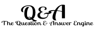
Dimension value
This is a numerical value that is assigned to the size, shape, or location of the feature being dimensioned. Dimensions are expressed in specific units on the drawing with relevant information.
Dimension Lines
Dimension lines are the thin continuous lines that show the extent and direction of the dimension. These lines should be placed 8mm to 10 mm away from the outline of the drawing and should be placed uniformly 6mm to 8mm from each other. The dimension values are preferably placed near the middle of the dimension lines.
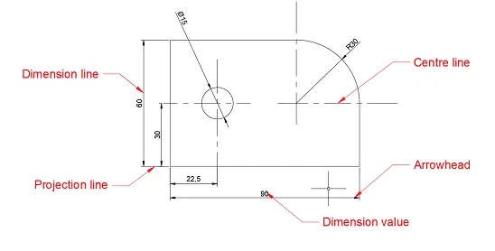
Projection Lines
Projection lines are thin continuous lines that are stretched out from the outlines for dimensioning and extended 2mm to 3mm beyond the dimension lines. These should be drawn in a direction perpendicular to the feature to be dimensioned. The dimension lines and projection lines should not intersect other lines unless this is unavoidable.
But in the case of special circumstances, the projection lines may be drawn in an oblique way, but parallel to each other.
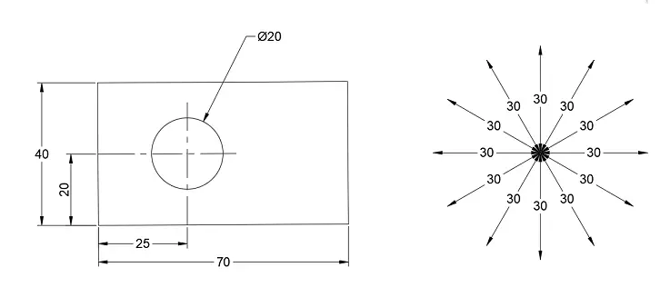
Leaders
Leaders are thin continuous lines and terminated by an arrowhead or dot referring to a feature and note. Figure and notes are written above the extended dimension line.
To avoid confusion leaders should not be –
- inclined at an angle less than 30°
- parallel to adjacent projection lines.
- parallel or adjacent dimensions.
Leaders are never drawn horizontal, vertical, curved, or freehand. They are generally drawn at any convenient angle 30°,45°, and 60°. Long leaders are generally avoided.
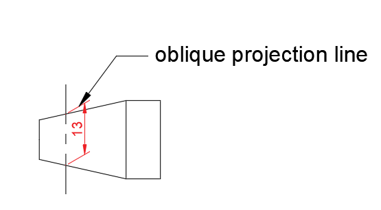
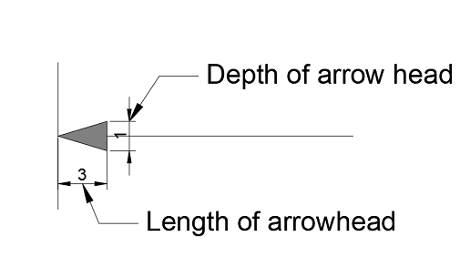
Arrowheads
Arrowheads indicate the termination points of dimension lines. They are typically open at an angle between 30° and 90° or closed and filled. For small drawings, arrowheads typically measure 3 mm in length, and for larger drawings, they are 5 mm.
The termination of dimension lines is indicated by arrowheads. The arrowheads may be open at a convenient angle of 30° to 90°, closed filled, or close blank. The closed filled arrowheads have a length of about three times the width/ depth and are generally preferred in the engineering drawing.
Generally, the length of the arrowhead for small drawing is 3 mm and for large drawing the length of the arrowhead is 5 mm.
When the space to accommodate the termination of arrowheads is insufficient, oblique stroke and points may be used.
Methods of Dimensioning in Engineering drawing:
Dimensioning can be done in one of two primary systems, as recommended by SP 46-2003 for Engineering Drawing Practice:
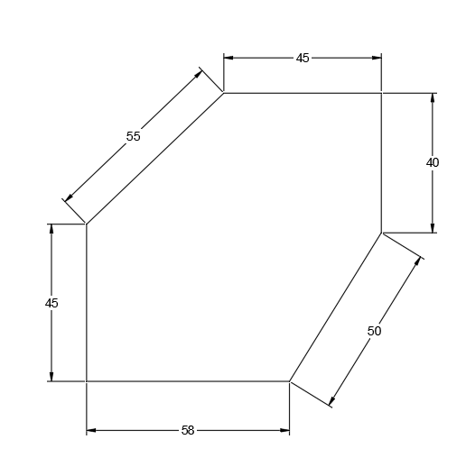
- Aligned System of Dimensioning
In this method, dimension text is placed parallel to the dimension line and is positioned preferably in the middle. This system allows dimensions to be read either from the bottom or from the right-hand side of the drawing.
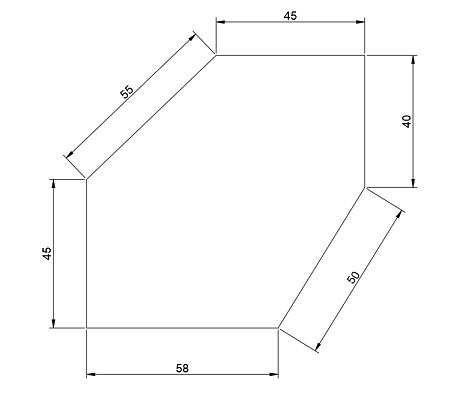
- Linear Dimensioning: Dimensions indicating the straight-line measurements.
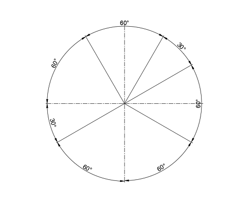
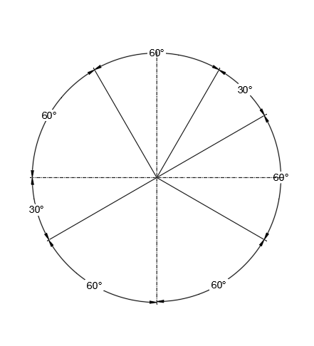
- Angular Dimensioning: Dimensions for angles between two lines.
Linear dimensioning
Angular dimensioning
2. Unidirectional System of Dimensioning
In this method, the dimensions are placed so that they are readable only from one direction, typically horizontally.
- Angular Dimensioning: Dimensions indicating angles.
- Linear Dimensioning: Dimensions indicating straight-line measurements.
Angular dimensioning
Arrangements of Dimensions
When several dimensions are to be placed in an engineering drawing, those dimensions are to be arranged in such a way that it provides a unique explanation.
The classification of dimensioning on the basis of arrangement is as follows.
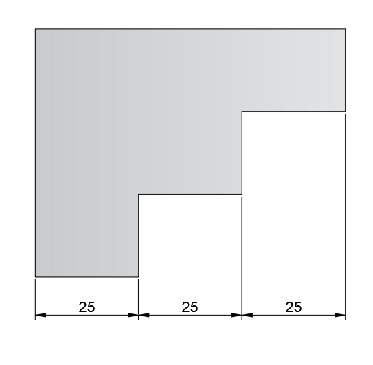
Chain dimensioning or Continuous dimensioning
In this method, successive dimensions are arranged in a continuous straight line.
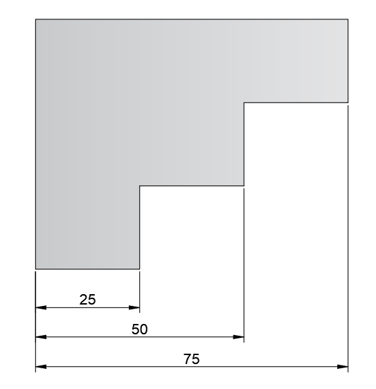
Parallel dimensioning or progressive dimensioning
In this method, a number of single dimensions parallel to one another are placed from a common origin. This method is adopted where a number of dimensions have a common origin. The cumulative error can be avoided by following this method.
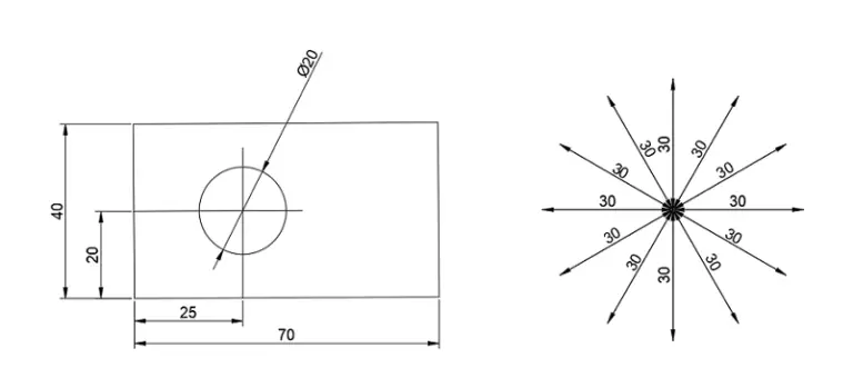
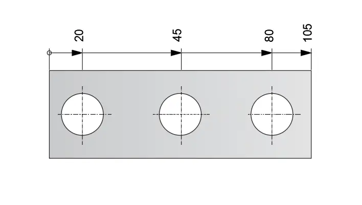
Running dimensioning or Superimposed dimensioning
In this method of dimensioning, all the dimensions begin from a common origin, which is indicated by a small circle of 3mm diameter, and terminated with arrowheads where individual dimension ends.
The dimension texts are rotated through 90° and placed in-line with the expansion line or above the dimension line near the arrowhead.
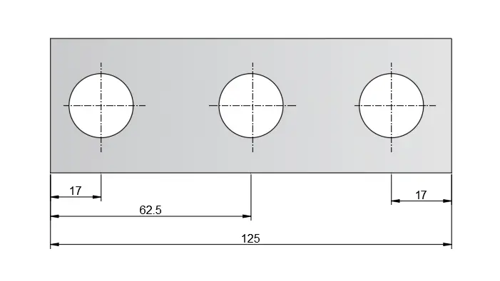
Combined dimensioning
In this arrangement of dimensions, there is the simultaneous use of parallel dimensioning, chain dimensioning, and running dimensioning in a single drawing.
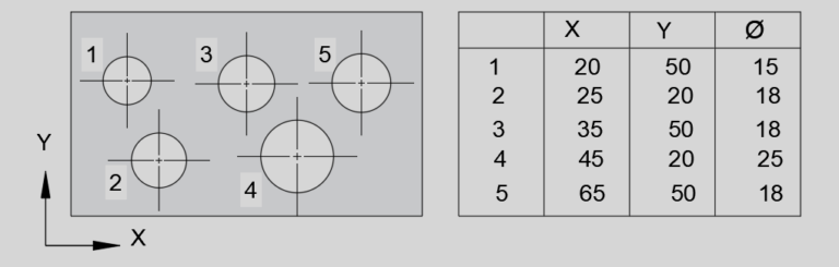
Coordinate dimensioning
Whenever a part is having too many dimensions, it is easier to read the drawing by the coordinate dimensioning method.
Example: A plate with many many holes can be easily read using the coordinate dimensioning method. Other styles of dimensioning will provide an overly cluttered result in this case.
In this system, origin and other features are to be numerically leveled. A coordinate table contains all the dimensional details to be placed near the drawing.
Rules of Dimensioning in Engineering Drawing
To follow a set of standard dimensioning rules is very crucial as the dimensions are used to define the size characteristics of a drawn object such as length, height, breadth, radius, diameter, angle, etc with lines, notes, and symbols.
The Bureau of Indian Standards (BIS) suggests the rules of dimensioning in engineering drawing in its bulletin IS 11669:1986 ( Reaffirmed 1999).
IS 11669: 1986 (Reaffirmed 1999): General Principles of Dimensioning on Technical Drawings
Dimensioning Rules:
Following dimension rules should be observed while dimensioning:
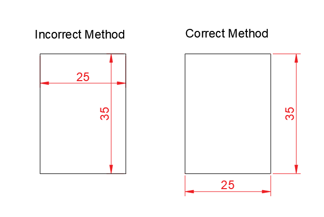
- Mark the dimension outside the figure or view. However, in the case of Dimensioning the radius of an arc or circle, it may be shown inside.
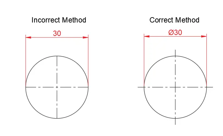
2. Dimensioning rules for Circle: A circle has to dimensioned by its diameter symbol Ø. The symbol Ø has to place before the dimension value.
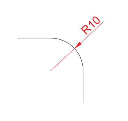
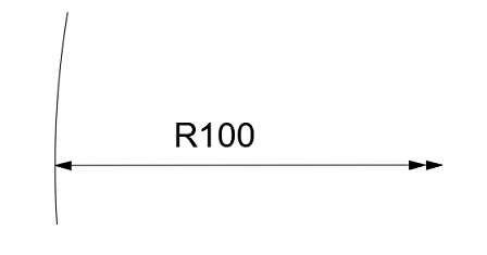
An arc has to dimensioned by its Radius symbol R.
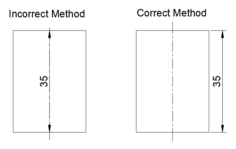
3. Dimensioning rules for Centerline:
i. The axis or centerline shall not be used as a dimension line with arrowheads at its ends.
ii. The axes or center lines must extend approximately 3 mm beyond the boundary of the part whose details they indicate.
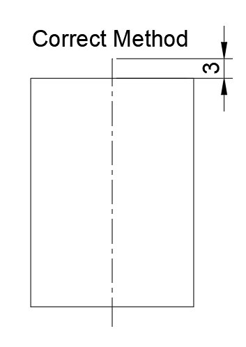
iii. Marking a dimension from a centerline is incorrect, except when the centerline passes through the center of a hole.
Also, an extended centerline may be served as an extension line.

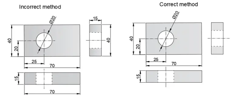
4. Dimensioning rules for Holes:
The center-to-center distance between the holes has to dimension in the view in which the holes are visible.
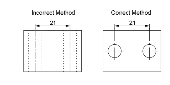
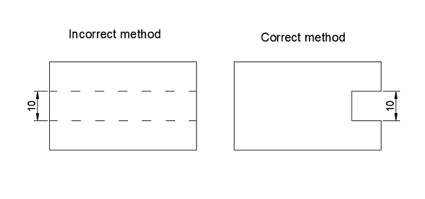
5. Dimensioning shall be done to the visible lines and not to the invisible or hidden lines.
6.The dimension value must be placed approximately 2 mm above the dimension line.
7.The extension line must extend 2 mm beyond the dimension line.
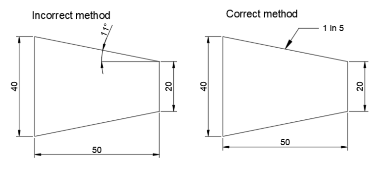
8.Dimensioning rules for Conical taper section:
The conical taper on diameter must be dimensioned as shown.
Conical Taper = (D-d)/L= 1 in n
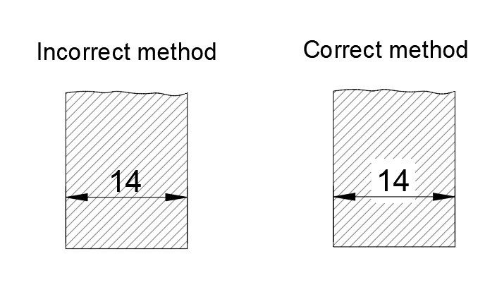
9.Dimensioning rules for Hatched portion:
When dimensioning within a hatched portion of a drawing, the hatching line should not cut the dimension text.
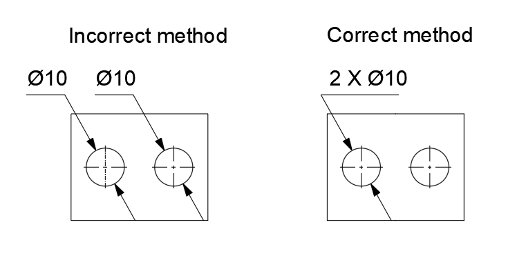
10.Dimensioning rules for Repeated features:
As far as possible dimensioning of repeated features of the same size is avoided.
The notes have to be written horizontally. The leader lines have to be inclined at an angle of 30°,45°, and 60° to the horizontal.
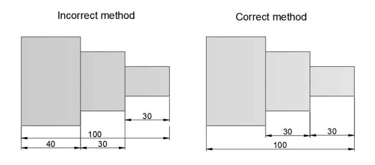
11.Overall dimensioning rules:
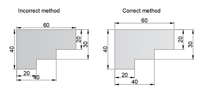
The overall dimensions have to be placed outside the intermediate dimensions.
The smaller dimensions must be placed nearer the view and the larger dimensions further away so that the extension lines or projection lines do not cross the dimension lines.
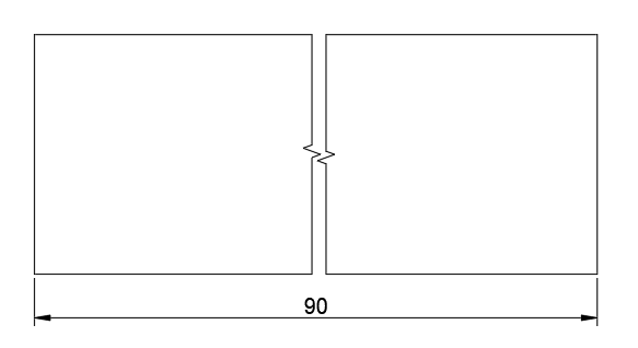
12. Dimension rules for a broken feature:
The dimension line should be shown unbroken where the figure to which it represents is shown broken.
13. When a dimension line cannot be completely drawn to its normal termination point, the free end must be terminated in a double arrowhead.
14. As far as possible, all the dimensions in a particular drawing should be in one unit only.
15.Dimensions indicated in one view need not be repeated in another view, except for the case of clarity and identification.
16. The dimensions must be placed on the view that most clearly shows the corresponding features.
17. The drawing line should never be used as a dimension line or it should not coincide with a dimension line. The dimension line should be uniformly spaced throughout the drawing. Dimension lines should be 8mm to 10 mm from the outline of the drawing and 6mm to 8mm from each other.
18. The dimension text should be placed preferably near the middle. If unavoidable due to lack of space, the dimension text may be placed above the extended portion of the dimension line beyond the arrowheads, preferably on the right-hand side.
Common Mistakes in Dimensioning and How to Avoid Them
While dimensioning is a standard practice, mistakes can still occur, especially for beginners. The following common errors can lead to misinterpretation or manufacturing errors:
- Overdimensioning
Overdimensioning occurs when unnecessary or redundant dimensions are added to the drawing. This can create confusion and make it harder for the manufacturer to interpret the drawing correctly. To avoid overdimensioning, ensure that each dimension provides essential and unique information that’s not already implied by another dimension. - Underdimensioning
Underdimensioning occurs when key features or measurements are omitted from the drawing, which can lead to incorrect fabrication. Always double-check that all critical dimensions, especially those related to functionality and fit, are included on the drawing. - Incorrect Placement of Dimensions
Placing dimensions in the wrong location can make them difficult to read and may lead to confusion during manufacturing. Dimensions should always be placed outside the object, except when dimensioning the radius of arcs or holes, which can be placed inside the drawing. - Unclear or Inconsistent Units
Using inconsistent units on the same drawing or failing to specify the units used can result in significant errors. Always use consistent units across the drawing and clearly specify the unit system (e.g., millimeters, inches) at the top of the drawing. - Ambiguous Tolerances
Providing unclear or absent tolerances can create problems during production. Clearly specify the tolerances to ensure that parts fit together as intended, especially when parts are to be assembled in a specific way or must meet strict operational standards.
Advanced Dimensioning Practices for Complex Systems
In large-scale systems, such as automotive or aerospace designs, advanced dimensioning techniques are essential for creating comprehensive and unambiguous engineering drawings. Some of these practices include:
- Assembly Drawings and Sub-Assemblies
For large systems composed of multiple parts, it’s often necessary to create assembly drawings that show how parts fit together. These drawings can be supplemented with sub-assembly drawings, which break down the assembly into smaller groups of components. Dimensioning here requires showing how different parts fit within the larger assembly and ensuring clear tolerances for fit and alignment. - Exploded Views
Exploded views can be useful for demonstrating how different parts come together. Dimensioning in exploded views requires careful attention to detail, ensuring that each part’s relationship to other parts is accurately represented while maintaining clear dimensions for assembly. - 3D Models and CAD Tools
With the rise of Computer-Aided Design (CAD) tools, engineers can now create 3D models of parts and assemblies, which can be dimensioned digitally. These tools often allow for automatic generation of 2D technical drawings, where dimensions are automatically placed and adjusted as the model changes. While this increases efficiency, it still requires manual oversight to ensure accuracy and compliance with dimensioning standards.
Best Practices for Dimensioning in Engineering Drawings
To ensure clarity and reduce the chance of errors in your engineering drawings, here are some best practices to follow:
- Always Use Standardized Symbols and Notations
Follow the prescribed symbols, notations, and conventions, such as ISO, BIS, and ASME standards, when dimensioning. This ensures uniformity across all drawings and makes the drawing easier for others in the field to interpret. - Group Related Dimensions Together
When dimensioning, try to group related dimensions together to reduce clutter. This makes the drawing easier to follow and minimizes the chance of errors during interpretation. - Use the Most Readable View
Place dimensions on the view that most clearly shows the feature in question. Avoid placing dimensions on hidden features or views that are difficult to interpret. - Avoid Overuse of Leader Lines
While leader lines can be helpful for pointing to features, overusing them can create clutter. Only use leader lines when necessary, and ensure they point to the appropriate feature.
Conclusion
Dimensioning is an integral part of engineering drawing and design. Proper dimensioning ensures that all features of an object are clearly defined, minimizing errors during production and ensuring that parts fit together and perform as intended. By following the principles and best practices of dimensioning, engineers can produce drawings that are clear, precise, and effective in conveying design intent.
Whether it’s a simple mechanical part or a complex system, attention to detail in dimensioning is essential for achieving the desired results in manufacturing and assembly. By adhering to standard practices and avoiding common errors, engineers can create dimensioned drawings that contribute to high-quality products and efficient manufacturing processes.
