In engineering, lines play a crucial role in communicating designs, specifications, and technical details. Whether you’re working on a blueprint, CAD model, or technical drawing, understanding the various types of lines is fundamental. From solid lines to dashed ones, each type has a specific purpose and meaning.
In this detailed guide on different types of lines in engineering drawing, we will discuss line types, their designation, and configuration and general drafting rules for the drafting of different types of lines used in –Technical drawing, Mechanical engineering drawing, and construction documentation.
Definition of Engineering Lines
Engineering lines are precise and standardized symbols used to represent different features, objects, and relationships in engineering drawings.
These lines are typically drawn using specific line types and thicknesses to convey different meanings. By utilizing a combination of lines, engineers can create detailed drawings that accurately represent the intended design.
Importance of Engineering Lines
The use of proper engineering lines is crucial in conveying information accurately and precisely. Engineering drawings serve as a primary communication tool among professionals involved in various stages of a project. Clear and understandable lines help prevent misinterpretation and errors during manufacturing, construction, or assembly processes.
What are the Lines?
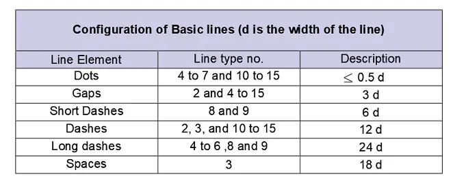
The lines are the geometrical objects whose length is more than half of the line width. A line connects an origin with an end in any way. A line can be a straight line or a curved line.
In the case of a line forming a circle, the origin of the line and the ending of the line may coincide with each other.
What is a dot?
The dot is a line, the length of which is less than or equal to half of the line width.
Read Also : Scales in Engineering drawing
Classification of Engineering Lines
Engineering lines can be classified into several categories based on their purpose and representation. Let’s explore some of the most common types of lines used in engineering drawings:
Visible Lines
Visible lines are the most fundamental type of lines used in engineering drawings. They represent the visible edges, boundaries, and outlines of objects. There are different subcategories of visible lines:
Object Lines
Object lines are solid lines used to depict the visible edges and boundaries of an object. These lines provide a clear representation of the object’s shape and outline.
Hidden Lines
Hidden lines are used to represent features or edges that are not visible from a particular viewpoint. They are typically represented using short dashes or dotted lines.
Center Lines
Center lines are used to indicate the center of symmetrical objects or the center axis of cylindrical or circular shapes. They are drawn using a long dash followed by a short dash pattern.
Dimension Lines
Dimension lines are used to indicate the sizes and measurements of objects or features. They are typically labeled with numerical values and arrowheads to indicate the extent of the dimension.
Invisible Lines
Invisible lines are used to represent features that are not physically present but are essential for understanding the design or construction. Some common types of invisible lines include:
Phantom Lines
Phantom lines are used to represent alternate positions, repetitive features, or hypothetical elements. They are often drawn using long dashes alternating with pairs of short dashes.
Cutting Plane Lines
Cutting plane lines are used to indicate the location and direction of a section or cut through an object. They help visualize internal details that are not directly visible.
Projected Lines
Projected lines are used to represent the outlines or boundaries of features that are projected onto a different plane. Two common types of projected lines are:
Section Lines
Section lines are used to indicate areas that have been cut through a solid object in a sectional view. These lines help differentiate between different materials or components within the object.
Break Lines
Break lines are used to show a portion of an object that has been intentionally removed to simplify the drawing. They help reduce the complexity of the drawing while still conveying the necessary information.
Auxiliary Lines
Auxiliary lines are used to provide additional information or assist in the creation of drawings. Some common types of auxiliary lines include:
Construction Lines
Construction lines are lightly drawn lines used as guides during the creation of a drawing. They are typically temporary and help align and position different elements accurately.
Leaders and Landing Lines
Leaders and landing lines are used to connect notes, labels, or dimensions to specific features or objects. They help identify and clarify the relationship between the annotation and the associated element.
Tangent Lines
Tangent lines are used to represent the point of contact between two curves or surfaces. They help define the precise intersection or touchpoints accurately.
Different types of line in engineering drawing
The engineering drawings are prepared with the help of different types of lines. For a full representation of an engineering drawing, different types of lines are adopted. Hence the selection of different line types in engineering drawing works becomes very important.
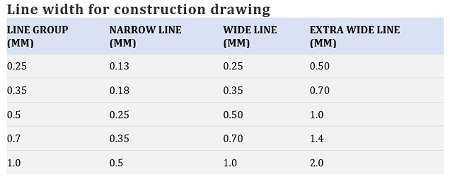
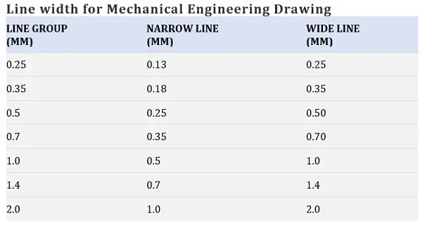
The selection of the width of the line depends on the scale, size, and type of the drawing. The width of the line should be chosen from one of the following.
0.13 mm, 0.18mm, 0.25 mm, 0.35 mm, 0.50mm, 0.70mm, 1.0mm, 1.4 mm, and 2.0 mm.
The series is based on the common ratio of 1:√2 or 1:1.4. Generally, lines of three different widths specified as extra-wide, wide, and narrow lines are used in engineering drawing works.
For construction drawing:
The widths of extra-wide, wide, and narrow line are in the ratio of 4:2:1.
A special width is adopted for the representation and lettering of graphical symbols.
The line width of these types of lines is situated between the width of the narrow line and the wide line.
For Mechanical engineering drawing:
On mechanical engineering drawing, two types of line width are generally used. The ratio between those two types of line width has to be 1:2.
Application of popular types of drawing lines
- In A1 and A2 drawing sheets, the wide lines should have a width of 0.7 mm, and the narrow lines have a width of 0.35 mm.
- The directly visible edges of an object represented by a line type called outlines. The continuous wide line is used to draw outlines.
- The dashed narrow lines are used to represent the edges that are not directly visible. In this type of line, the dashes are about 2 mm long with spacing between the two dashes of about 1 mm.
- The long dashed-dotted narrow line is used to represent the axis of an object and centers of circles and arcs. The long dashes are about 10 mm long and the spaces between the long dash and dot are about 1 mm.
- The continuous narrow lines are used for dimension lines, construction lines, and leader lines.
- The line type for representing surfaces in section views resulting from cutting called hatch lines. In hatching the distance between two parallel lines is about 1 mm to 2mm.
The colour of line types
The lines have to be drawn in black and white depending on the color of the background. Other standard colors may also be used. In such a case, the meaning of colors has to be explained.
Rules for drafting for different types of line
The following rules should be maintained while drafting different types of lines in engineering drawings.
- The lines should be drawn in white or black depending on the color of the background.
- The minimum spaces to be maintained between parallel lines should preferably be greater than 0.7 mm.
- The dotted line should preferably meet at a dot. Other types of lines should preferably intersect or meet at a dash.
- In case of two or more lines of different type which may overlap or coincide, the drawing priority may be given in the following order:
(a) Visible outlines and edges
(b) Hidden outline and edges
(c) Cutting planes
(d) Centre lines and lines of symmetry.
(e) Centroidal lines
(f) Projection lines
For example, If a visible line overlaps with a centerline, then only a visible line is to be drawn ignoring the hidden line. Similarly, if a cutting plane line coincides with a projection line, then only a hidden line is to be drawn ignoring the projection line.
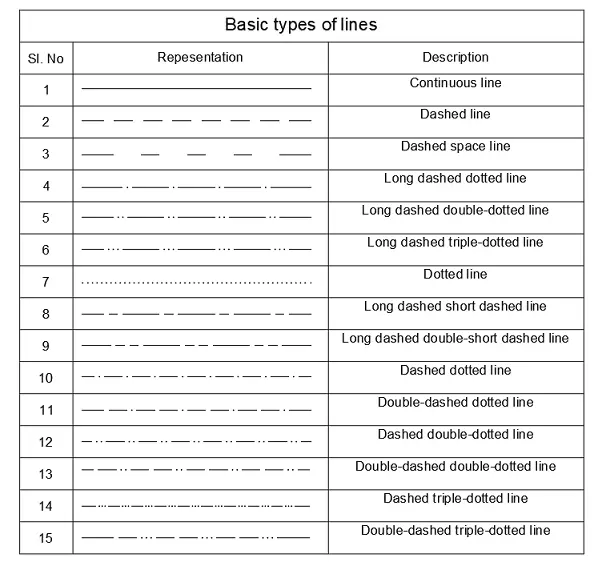
Basic types of lines
In a well-executed engineering drawing, each line has a specific meaning and function. The line types for engineering drawing as recommended by BIS are as follows.
The final drawings are drafted with pencil, are generally divided into 2 line groups. It is very essential to maintain all the drawing lines except construction lines should be uniform, clean, and dense. The construction lines should be thin and faint. The construction lines should be drawn in such a way that they are hardly visible in a finished drawing.
The pencils used for engineering drawing are graded according to their relative hardness. The drawing pencils are generally marked as H, 2H, 3H, 4H, etc.
- H pencil– Initial work and construction lines
- 2H pencil– cut lines, dotted lines, section plane lines, dimension lines, arrowheads.
- 3H or 4H pencil– center lines, section lines.
General application of different line types in Construction Drawings:
Continuous narrow lines:
The application of continuous narrow lines are as follows:
- Dimension line, extension line, and arrowheads.
- Projection line
- Hatching
- Leader line
- Gridlines
- Short centrelines
Continuous wide lines:
The application of continuous wide lines are as follows:
- Visible outlines and edges of a part.
- For representing the visible outlines of parts in cut and section when hatching is used.
- System lines in structural and metal engineering.
- Arrow lines for representing views, cuts, and sections.
- Proposed contours on landscape drawings.
Continuous extra-wide lines:
- To represent the visible outlines of parts in cut and section when hatching is not used.
- Reinforcement bars.
Dashed narrow line:
- To represent hidden edges and outlines.
Dashed Wide line:
- To represent the permissible areas of a surface treatment.
Long-Dashed dotted narrow line:
- To represent a pitch circle of gears and holes.
- Line of symmetry and center lines.
Long-Dashed dotted wide line:
- To represent the indication of cutting planes.
Long-Dashed double-dotted narrow line:
- To represents the centroidal lines.
- Outlines of adjacent parts and alternate execution.
- To indicate initial outlines prior to forming.
Conclusion
In conclusion, understanding the various types of lines used in engineering drawings is crucial for accurate communication and interpretation of technical information. Each type of line serves a specific purpose and provides essential details about objects, features, and relationships.
By utilizing the appropriate lines, engineers and designers can convey their ideas effectively, leading to successful manufacturing, construction, and design processes.
Read Also : How to measure the height of a building indirectly
Some Special Types of Lines
Hidden line:
The hidden lines are used to represent an object which is hidden from the view. Hidden lines are used to show hidden surfaces, edges, or corners of an object.
Centre line:
The hidden lines are used to represent an object which is hidden from the view. Hidden lines are used to show hidden surfaces, edges, or corners of an object.
Symmetry line:
The symmetry lines are adopted to represent the partial views of symmetrical parts. The symmetry is a center line with two thick short parallel lines drawn at right angles to it at the both ends.
Extension and dimension line:
For dimensioning an object in Engineering drawing extension and dimension lines are used.
Leader line:
The leader lines are used to indicate a part of a drawing to a reference note. The leaders with arrowheads touch the object line and the leader with dot rests on the object surface.
Break line:
Break lines indicate the shorten views of a long part.
Cutting-plane line:
The cutting-plane lines are used to indicate the position of an imaginary cutting plane. The cutting plane is used to reveal the interior details of an object.
Chain line:
The chain lines are adopted to represent a zone or surface of special or additional consideration.
Stitch line:
The stitch lines are used to indicate a stitching process or a view representating stitching process.
Phantom line:
The phantom lines are used to represent the details of the alternate positions of a moving part or repetitive parts.
Viewing-plane line:
The viewing-plane lines represent the direction of the view when a partial view is used,
Read Also : How to measure the height of a building indirectly
Frequently asked types of line
Read Also : How to measure the height of a building indirectly
What are engineering lines?
Engineering lines are graphical representations used in technical drawings to communicate information about the shape, size, and features of objects.
Why are engineering lines important?
Engineering lines are important because they accurately convey information and prevent misinterpretation and errors during manufacturing, construction, or assembly processes.
What are visible lines in engineering drawings?
Visible lines represent the visible edges, boundaries, and outlines of objects in engineering drawings.
What are hidden lines?
Hidden lines are used to represent features or edges that are not visible from a particular viewpoint.
What are center lines?
Center lines indicate the center of symmetrical objects or the center axis of cylindrical or circular shapes.
What are dimension lines used for?
Dimension lines are used to indicate the sizes and measurements of objects or features.
What are phantom lines?
Phantom lines are used to represent alternate positions, repetitive features, or hypothetical elements in engineering drawings.
What are cutting plane lines?
Cutting plane lines indicate the location and direction of a section or cut through an object.
What are section lines used for?
Section lines are used to indicate areas that have been cut through a solid object in a sectional view.
What are break lines?
Break lines are used to show a portion of an object that has been intentionally removed to simplify the drawing.

