
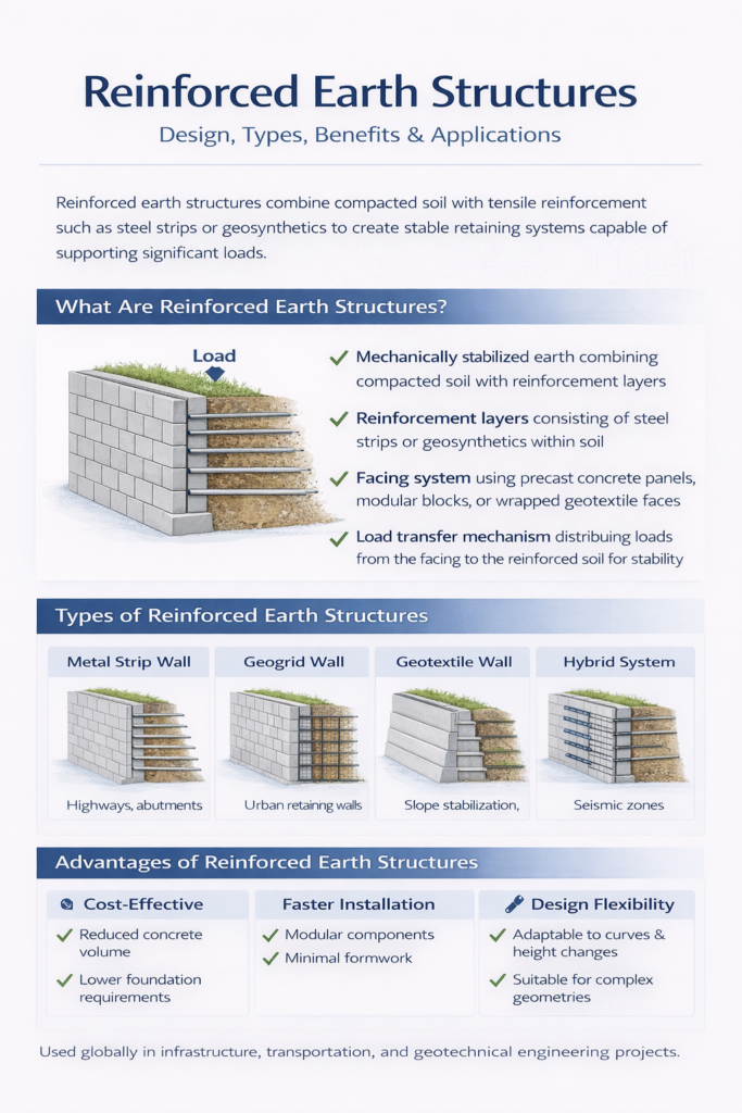
Reinforced earth structures combine soil with tensile reinforcements—like steel strips, geogrids, or geotextiles—to create a composite material that behaves like a strong, flexible, and economical wall or embankment. They’re used globally in highways, retaining walls, bridge abutments, and railways to resist lateral earth pressure and improve stability even on weak foundations.
Key Takeaways:
- They blend soil’s compressive strength with reinforcement’s tensile capacity.
- Offer lower cost, faster construction, and high seismic resistance.
- Adaptable for US, EU, India, and Asia through region-specific materials and codes.
- Widely used for transportation, energy, and flood-control projects.
- Comply with design standards like AASHTO (US), Eurocode 7 (EU), and IRC 78 (India).
Reinforced earth structures represent one of the most revolutionary geotechnical innovations since the mid-20th century—bridging the gap between soil mechanics and modern infrastructure design.
Let’s explore it further below.
What Is a Reinforced Earth Structure?
A reinforced earth structure (RES) is a mechanically stabilized soil (MSS) system where soil’s inherent strength is enhanced using tension-resisting materials such as galvanized steel strips, polymer geogrids, or geotextiles. The reinforced soil mass and facing panels act together to form a flexible, durable retaining structure.
The fundamental concept is that soil can withstand compression but not tension. By introducing reinforcement layers, engineers transform the soil into a composite material with improved shear strength and deformation control.
In essence:
- Reinforcements absorb tensile stress.
- Soil provides confinement and frictional resistance.
- Facing elements (concrete panels, blocks, or wrapped geotextiles) protect and retain the soil.
Applications include:
- Retaining walls for highways and railways.
- Bridge abutments and ramps.
- Slope stabilization.
- Embankments over soft soils.
- Coastal and flood-control levees.
The modern concept of reinforced earth was patented by Henri Vidal in 1963, but similar soil-reinforcement techniques existed in ancient Asia, where bamboo mats strengthened river embankments.
How Reinforced Earth Works: The Engineering Principle
The performance of reinforced earth relies on soil-reinforcement interaction through friction and passive resistance. The reinforcement layers are placed horizontally within compacted soil, creating a composite mass that can resist both internal and external failure modes.
Mechanics of Reinforcement:
- Load Transfer: External loads (from soil or surcharge) are transferred to reinforcements through shear at the soil-reinforcement interface.
- Tensile Resistance: Reinforcements resist tension, reducing lateral earth pressure on the facing.
- Composite Action: The combined behavior enhances stability against sliding, overturning, and bearing failure.
A simplified design approach uses limit equilibrium and earth-pressure theories. The internal stability checks include:
- Pullout resistance of reinforcement.
- Tensile rupture strength.
- Connection strength at facing.
The external stability includes:
- Base sliding and overturning checks.
- Global stability using slope-stability analysis.
- Bearing capacity evaluation.
Reinforced earth walls can tolerate up to five times more settlement than conventional gravity walls without distress—making them ideal for soft-soil regions in India and Southeast Asia.
Types of Reinforced Earth Structures
Reinforced earth systems vary depending on reinforcement type, facing type, and construction method. Broadly, they can be categorized as follows:
| Type | Reinforcement | Facing | Typical Use |
|---|---|---|---|
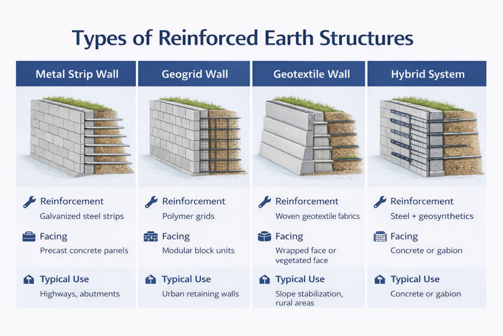
| Metal Strip Wall | Galvanized steel strips | Precast concrete panels | Highways, abutments |
| Geogrid Wall | Polymer grids | Modular block units | Urban retaining walls |
| Geotextile Wall | Woven fabrics | Wrapped face or vegetated face | Slope stabilization, rural areas |
| Hybrid System | Steel + geosynthetics | Concrete or gabion face | Seismic zones |
1. Steel-Reinforced Earth Walls
Used extensively in the US and EU, these walls utilize galvanized or stainless steel strips, offering high strength and long design life. They comply with AASHTO LRFD and EN 14475 standards.
2. Geosynthetic-Reinforced Soil (GRS)
Common in India, Japan, and Southeast Asia, GRS walls use polymer geogrids or woven geotextiles that resist corrosion and adapt to differential settlement—especially in humid or coastal climates.
3. Wrapped-Face Systems
Economical and eco-friendly, these use wrapped geotextile layers and vegetation for slope stability. They blend well with the environment and are popular in rural roads under India’s PMGSY program.
Japan pioneered the use of full-height geogrid reinforcements for high-seismic retaining walls after the 1995 Kobe earthquake, drastically reducing wall failures in subsequent quakes.
Advantages of Reinforced Earth Structures
Reinforced earth structures outperform traditional retaining systems in multiple ways, both technically and economically.
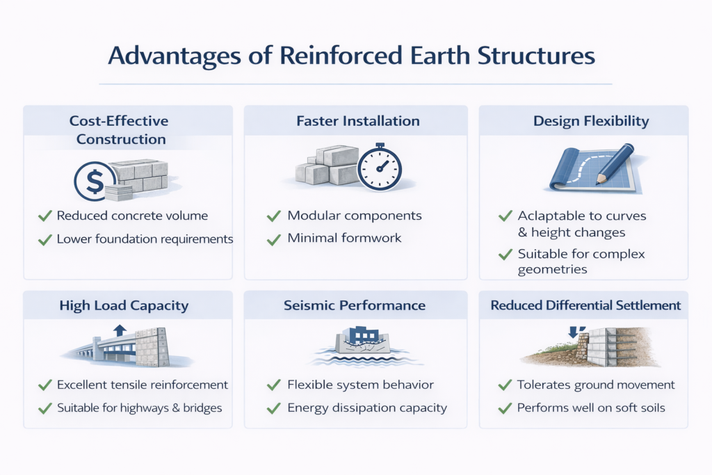
1. Cost and Time Efficiency
- Require less concrete and steel than gravity walls.
- Rapid modular construction reduces project duration by up to 40%.
- Minimal excavation and backfill compared to conventional retaining walls.
2. High Flexibility and Seismic Resistance
- Can absorb large differential settlements and seismic loads.
- Modular facing allows for easy repair and adaptation.
- Extensively used in California, Turkey, and Japan, known for high seismic activity.
3. Sustainability and Environmental Benefits
- Local soil can be reused as backfill, reducing carbon footprint.
- Vegetated facings promote biodiversity and stormwater control.
- Lower embodied energy than reinforced concrete systems.
4. Aesthetic and Functional Versatility
- Multiple facing options—textured concrete, stone, or green vegetated walls.
- Ideal for highway ramps, bridge abutments, and urban landscaping.
5. Global Performance Consistency
- Proven success across climates: from US deserts to tropical Asia and European alpine terrains.
According to World Bank project data, the average life-cycle cost of reinforced soil walls is 25–35% lower than that of reinforced concrete retaining walls over 50 years.
Global Design Standards for Reinforced Earth Structures
Reinforced earth design is standardized internationally under various geotechnical and structural codes, ensuring global reliability and safety. Each region follows its unique framework, but the fundamental principles—limit equilibrium and deformation control—remain the same.
1. AASHTO LRFD (United States)
The American Association of State Highway and Transportation Officials provides guidelines under Section 11 (Walls and Abutments).
Key features include:
- Load and Resistance Factor Design (LRFD) approach.
- Pullout and rupture limit states for reinforcements.
- Service limit states for wall deformation and settlement.
- Typical design life: 75–100 years with corrosion protection.
2. Eurocode 7 and EN 14475 (European Union)
Europe adopts a limit-state design concept focusing on both structural and geotechnical reliability.
- Reinforcement spacing and facing design per EN 1997-1.
- Use of corrosion-resistant or polymeric reinforcement materials.
- Partial factors calibrated for soil variability.
- Sustainability emphasized via Environmental Product Declarations (EPDs).
3. IRC 78 and BIS Codes (India)
India’s Indian Roads Congress (IRC) and Bureau of Indian Standards (BIS) have issued detailed guidance:
- IRC 78: Design & Construction of Reinforced Soil Walls.
- IS 14458: Reinforced Soil Retaining Structures — Design and Construction.
- Encourages use of locally available fill and polymer reinforcements to reduce cost.
4. Asian and Middle Eastern Standards
Japan, Korea, and Singapore use hybrid standards combining AASHTO and Eurocode concepts, emphasizing seismic design and tropical durability.
Middle Eastern nations (e.g., UAE, Saudi Arabia) follow BS 8006-1 or its local adaptations for highway infrastructure.
In Japan, reinforced soil abutments are often designed with “zero bridge-seat movement” criteria—meaning they can withstand full seismic displacement without joint failure.
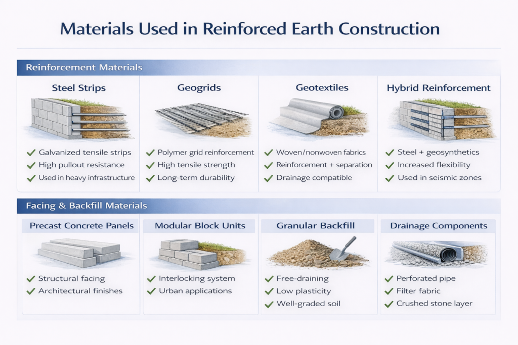
Materials Used in Reinforced Earth Construction
The performance of a reinforced earth structure depends heavily on material selection—both for the reinforcement and the fill.
1. Reinforcement Materials
| Type | Material | Advantages | Typical Region |
|---|---|---|---|
| Metallic Strips | Galvanized or stainless steel | High tensile strength, long lifespan | US, EU |
| Geogrids | HDPE, PET, or PP polymers | Lightweight, corrosion-free | India, Asia |
| Geotextiles | Woven or nonwoven fabrics | Cost-effective, flexible | India, Africa |
| Geostrips/GeoComposites | Multi-layer synthetic bands | Customizable stiffness | Global |
Reinforcement selection is based on tensile strength, creep resistance, corrosion durability, and interface friction angle.
2. Backfill Materials
The backfill should have:
- High friction angle (φ ≥ 30°).
- Low plasticity index (PI ≤ 6).
- Controlled moisture for compaction.
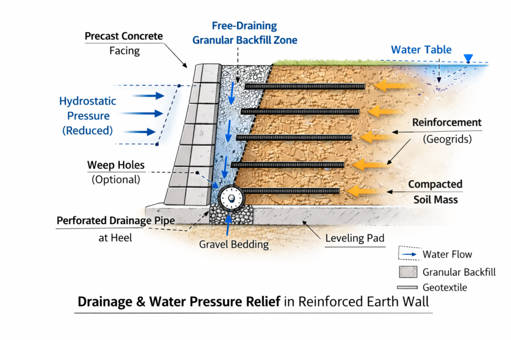
- Free-draining nature to minimize pore pressure.
Locally sourced granular soil or well-graded sand is often sufficient, provided it meets compaction and durability standards.
3. Facing Elements
Depending on site and aesthetics:
- Precast concrete panels for highways and abutments.
- Segmental concrete blocks for landscape walls.
- Gabions or vegetated wraps for environmentally sensitive zones.
India’s Konkan Railway and China’s expressway systems both rely on polymeric reinforced soil walls to withstand monsoon-driven erosion and seismic activity.
Design Considerations and Analysis Methods
Designing a reinforced earth wall involves analyzing external stability, internal stability, and connection performance.
1. External Stability Checks
- Sliding: Ensures resisting friction > lateral earth pressure.
- Overturning: Checks for adequate base width and reinforcement depth.
- Bearing Capacity: Evaluates foundation soil under maximum load.
2. Internal Stability Checks
- Pullout Resistance: Based on soil-reinforcement interface friction and embedment length.
- Rupture Strength: Tensile capacity of the reinforcement at design load.
- Connection Strength: Interface capacity between reinforcement and facing panels.
3. Global Stability
- Evaluated through circular or composite slip surface analysis using methods like Bishop’s or Morgenstern–Price.
- For critical structures, finite element analysis (FEA) provides deformation and strain distribution profiles.
Typical Design Parameters (for guidance only):
| Parameter | Recommended Range |
|---|---|
| Reinforcement spacing | 0.4–0.8 m |
| Reinforcement length | 0.6H to 0.7H (H = wall height) |
| Facing inclination | 70°–90° |
| Factor of safety | ≥ 1.5 (sliding/overturning) |
Finite element modeling has shown that geogrid-reinforced soil walls distribute stresses more uniformly, reducing face bulging by up to 30%.
Global Case Studies and Applications
1. United States — I-70 Colorado Highway Expansion
Over 80,000 m² of MSE walls were constructed using galvanized steel strips. The system resisted extreme temperature cycles and snow load while cutting retaining wall costs by 35%.
2. Europe — Lyon–Turin Rail Link (France–Italy)
Reinforced earth walls using polymeric geogrids were preferred for mountainous terrain. Eurocode-compliant design improved seismic resilience and environmental harmony.
3. India — Delhi Metro Rail and National Highways
India’s National Highways Authority (NHAI) and DMRC use reinforced soil abutments for elevated corridors. Locally available backfill reduced project cost by nearly 25%.
4. Japan — Kobe Earthquake Reconstruction
Following the 1995 disaster, Japan rebuilt key highway embankments using geogrid-reinforced soil systems—none of which failed during subsequent earthquakes.
5. Middle East — Dubai Metro and Riyadh Highways
High-strength PET geogrids and corrosion-proof facing units are used to handle high temperatures and saline soils.
Globally, reinforced earth technology has been used in more than 60 countries, covering over 40 million square meters of wall surface to date.
Common Mistakes to Avoid
1. Using Improper Backfill Materials
Low-quality or cohesive soils reduce friction and drainage capacity. Always choose granular or well-graded material with low plasticity and high shear strength.
Pro Tip: Avoid silty clays and organic soils—these trap moisture and accelerate failure.
2. Ignoring Corrosion and Durability Factors
Metallic reinforcements require proper galvanization or stainless steel coatings in humid or saline environments.
In tropical Asia, prefer polymeric geogrids that resist chemical and biological degradation.
3. Overlooking Drainage Design
Without efficient drainage, pore pressure builds up, reducing effective stress and stability.
Use perforated drains and geocomposite filters behind facings to prevent hydrostatic buildup.
4. Poor Compaction or Layer Control
Inconsistent compaction reduces pullout resistance and leads to settlement.
Maintain 95% of Modified Proctor Density in every layer.
5. Neglecting Maintenance or Inspection
Even the best-designed walls need monitoring.
Periodic inspection for facing displacement, vegetation growth, and joint corrosion ensures longevity.
Neglected drainage was identified as the top cause of reinforced soil wall failures in over 60% of post-construction audits worldwide.
Expert Tips to Remember
1. Design for Local Environment
Adapt design parameters to regional conditions—consider frost depth in Europe, seismicity in Japan, or monsoon effects in India.
2. Incorporate Sustainable Materials
Use recycled aggregates and nonwoven geotextiles to reduce embodied carbon while maintaining strength.
3. Validate Field Performance
Always confirm pullout resistance and tensile strength with on-site or laboratory testing before full-scale construction.
4. Prioritize Drainage and Waterproofing
Drainage systems should be integrated during construction, not retrofitted later.
5. Train Workforce on Reinforcement Placement
Misalignment of geogrids or metal strips drastically reduces performance.
Implement a quality assurance checklist for each reinforcement layer.
A 2023 European Geotechnical Journal study showed that trained installers improved wall performance by 18% compared to untrained crews.
FAQs
1. What is the main purpose of reinforced earth structures?
To enhance soil strength and stability by combining compressive soil properties with tensile reinforcement—creating a composite structure capable of resisting high lateral pressures.
2. How long do reinforced earth structures last?
When properly designed and maintained, they last 75–120 years, depending on material type and environmental exposure.
3. Are they cost-effective compared to concrete retaining walls?
Yes—studies show 25–40% lower life-cycle costs, faster construction, and easier repair or expansion.
4. What materials are used for reinforcement?
Common materials include steel strips, geogrids (HDPE, PET, PP), geotextiles, and geostrips—chosen based on corrosion resistance and tensile strength.
5. Can reinforced earth walls be used in seismic zones?
Absolutely. Their flexible nature allows them to absorb seismic energy, making them ideal for earthquake-prone regions like California, Japan, and Nepal.
6. What is the difference between reinforced soil and mechanically stabilized earth (MSE)?
Both terms describe the same concept. “Reinforced soil” emphasizes geotechnical mechanics, while “MSE” highlights structural design integration.
7. Do they require maintenance?
Minimal, but periodic inspection for drainage, facing integrity, and vegetation control ensures long-term performance.
8. Can local soils be used as backfill?
Yes, provided they meet gradation and strength criteria (friction angle > 30°, PI < 6). Using local materials reduces project cost and carbon footprint.
9. How do reinforced earth walls perform under heavy rainfall?
With proper drainage, they perform exceptionally well. Permeable backfill and filter layers prevent hydrostatic pressure and erosion.
10. What are the main global standards for design?
- AASHTO LRFD (US)
- Eurocode 7 + EN 14475 (EU)
- IRC 78 + IS 14458 (India)
- BS 8006 / JGS 0511 (Asia)
India’s 2025 Smart Highway Program mandates the use of reinforced earth technology in 60% of new retaining structures to reduce carbon emissions.
Conclusion
Reinforced earth structures have transformed how engineers design and build retaining systems across the globe. By blending soil and reinforcement, they deliver unparalleled strength, flexibility, and cost-efficiency—all while supporting sustainability goals.
From US interstates to Indian highways, European railways, and Asian metro systems, these structures stand as proof of how engineering innovation can harmonize with nature and economy.
The key lies in proper design, quality materials, and regular inspection—ensuring performance that outlasts generations.
Key Takeaways
- Reinforced earth combines soil and reinforcement into a composite strength system.
- Offers 25–40% cost savings and exceptional seismic resilience.
- Design per AASHTO, Eurocode, or IRC standards for global compliance.
- Choose materials based on regional climate and corrosion risk.
- Ensure proper drainage, compaction, and inspection for long-term performance.
- A sustainable, proven solution for the next generation of infrastructure worldwide.
