Quick answer
A scale in engineering drawings is a ratio that represents the proportional relationship between the actual size of an object and its depiction on paper. It allows large structures or tiny parts to be represented accurately and conveniently.
- Common types: Full scale (1:1), reduction (e.g., 1:100), and enlargement (e.g., 10:1).
- Purpose: Ensures clear communication of dimensions and design intent.
- Engineering scales: Often use decimal-based measurements for precision (e.g., 1″ = 10′).
- Importance: Critical for manufacturing, construction, and design accuracy.
Using the correct scale ensures drawings are both readable and usable for all project stakeholders.
As an engineering student, there are several essential tools that you need to excel in your studies. One of these tools is an engineering scale. A scale is a measuring instrument used to measure and draw accurate technical drawings. However, choosing the best engineering scale for your needs can be overwhelming. This article aims to guide you in selecting the best engineering scale for your studies by reviewing the top engineering scales on the market.
What is a scale in engineering drawings?
A scale in engineering drawings is a ratio that represents the proportion between the dimensions of the drawing and the actual dimensions of the object. It’s like when you see a map and realize that 1 inch on paper might represent 1 mile in the real world. In engineering, this concept is crucial because it allows us to create detailed and manageable drawings of large structures or tiny components.
The scales are the ratio of the linear dimension of an element of an object as represented in the original drawing to the actual linear dimension of the same element of the object itself.
How Does a Scale Work?
In simple terms, a scale works by shrinking or enlarging real-world measurements to fit on a drawing. For example, if you’re working with a scale of 1:100, it means that 1 unit on the drawing is equal to 100 units in real life. Pretty straightforward, right?
Why Is Scale Important in Engineering Drawings?
Imagine trying to fit an entire skyscraper on a standard sheet of paper without scaling it down. Impossible, right? That’s why scale is vital—it helps you represent large objects in a way that’s easy to understand and work with. Plus, it ensures everyone is on the same page (literally) when interpreting the drawing.
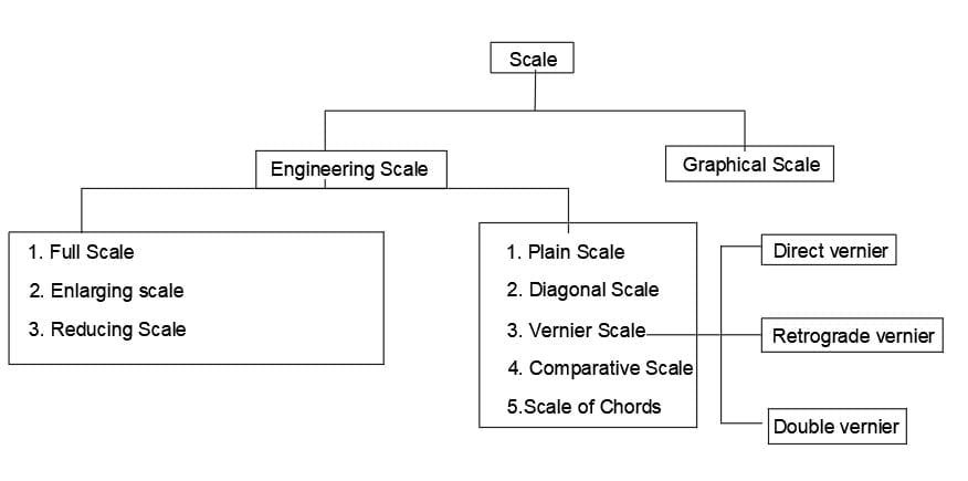
Full scale, Enlarging scale, and Reducing scales in Engineering drawing-
It is not always possible to draw an object to its actual size. For example, drawings of very large objects cannot be plotted in full size because they are too large to adjust on the drawing sheet. Again, drawing a very small object cannot be drawing in full size because it would be too small to draw and to read.
There are different types of scales in engineering drawing are used so that objects can be accommodated and comfortably be plotted and read are as follows:
Full scale: when an engineering drawing is prepared to the actual size of the object, the scale used is termed as full-size scale and the drawing is known as full-size drawing.
A scale with a ratio of 1:1 is known as a full-size scale in engineering drawing.
Example: A 30 mm radius plain disc is represented on the drawing by a circle of 30 mm radius.
Enlarging scale: When a very small object such as components of a wristwatch, is enlarged in some regular proportion to accommodate its drawing. So when the drawing is prepared larger than the actual size, the scale is said to be an enlarged scale, and the drawing is said to be an enlarged-sized drawing.
A scale in which the ratio is larger than 1:1.
Reducing scale: When the object is of large size, the actual dimensions of the object have to be reduced to accommodate the drawn object in the drawing sheet. So when a drawing is prepared smaller than the actual size of the object, the scale used is termed as reducing scale and the drawing is known as a reduced-sized drawing.
A scale in which the ratio is smaller than 1:1.
Representative Fraction(RF)
The representative fraction is defined as the ratio of the dimension of an element of an object in the drawing to its actual linear dimension of the same element of the object itself.

The value of R.F is always expressed in the form of x:y, in which both x and y are lengths converted into the same units. Hence RF has no decimal and it is unitless.
RF for full-sized scale =1
RF for reducing scale <1
RF for enlarging scale> 1.
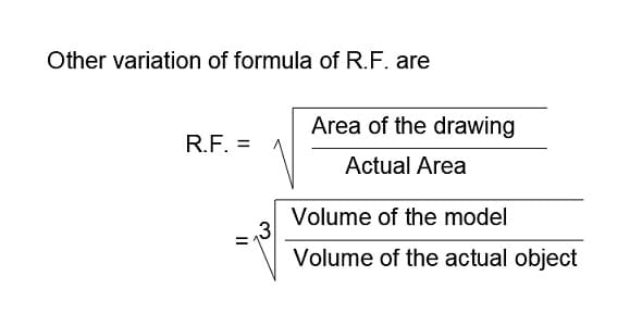
It is also highlighted that RF is the ratio of linear dimensions and not the ratio of areas or volumes. In case, the quantities are given in units of areas, then take the square root to convert them into lengths units. Similarly, if the quantities are given in units of volume, then take the cube root to convert them into lengths unit.
Designation of Scales in Engineering Drawing
The complete designation of an engineering scale shall consist of the word “SCALE’ followed by the mention of its ratio, as follows:
SCALE 1: 1 for full size;
SCALE X :1 for enlargement scales;
SCALE 1: X for reduction scales
BIS recommended Scales in engineering drawing
The standard values of RF for scales in engineering drawing as recommended by BIS are as follows.
- Full Scales- 1:1
- Reducing Scales – 1:2 , 1:5, 1:10 , 1:50, 1:100, 1:200, 1:1000, 1:2000, 1:5000
- Enlarging Scales- 50:1 , 20:1, 10:1, 5:1, 2:1.
The scales in engineering drawing have to be chosen for depends upon various factors like the size of the object, functionality of the drawing.
The requirement for the construction of a scales in engineering drawing.
The information required for the construction of plain, diagonal, or a vernier scales are as follows:
- Rf of the Scale
- The maximum length to be measured by the scale.
- The minimum length to be measured by the scale (i.e., Least count)
The length of the scales in engineering drawing is determined by the formula:
length of the scale= representative fraction x Maximum length to be measured.
Read Also : Why is Lettering Important in Engineering Drawing?
Types of scale in engineering drawing
The scales in engineering drawing are classified as the following:
- Plain scale
- Diagonal scale
- Vernier scale
- Comparative scale
- Scale off chords
Plain scale
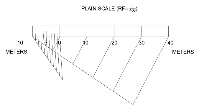
In a plain scale a line divided into a suitable number of equal parts or units, the first of which is subdivided into smaller parts.
The use of plain scale in engineering drawing is to measure up to two consecutive units, i.e., a unit and its immediate subdivision.
For Example – meter and decimetre, feet and inches, etc.
Diagonal scale
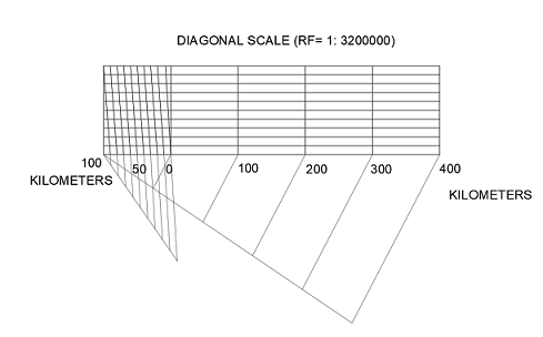
A diagonal scale in engineering drawing is used when the measurements are required in three consecutive units; i.e., a unit and its immediate two subdivisions. A diagonal scale’s measurement is more accurate than a plain scale’s measurement.
For example, meter, decimeter, and centimeter.
Vernier scale
A vernier scale is used to measure three consecutive units of a metric scale. Hence, the accuracy in measurement of the vernier scale is equivalent to that of a diagonal scale. The vernier scales in engineering drawing is used to indicate the distances in a unit and its two immediate subdivisions.
The vernier scales consists of two parts : (a) main scale and (b) vernier scale.
The vernier is an auxiliary scale that is attached at one end f the main scale. As it is difficult to subdivide the minor divisions of the main scale in an ordinary way, it is done with the help of the vernier.
Mostly, the vernier scale is used on length measuring devices such as vernier calipers, screw gauges, and micrometers.
Direct vernier scale or forward vernier scale
In direct vernier, the smallest division of the main scale is greater than the smallest division of vernier scale.
The smallest division of the main scale (x)>The smallest division of the vernier scale(y).
The least Count of the direct vernier; (x-y)
Retrograde vernier scale or backward vernier scale
In Retrograde vernier, the smallest division of the main scale is smaller than the smallest division of vernier scale.
The smallest division of the main scale (x)<The smallest division of the vernier scale(y).
The least Count of the direct vernier; (y-x)
Double vernier scale
In the double vernier, two simple verniers are placed from end to end to form a single scale with zero at the center. One vernier is used for taking readings in the clockwise direction and the other vernier is used for taking readings in the anti-clockwise direction.
When the graduations on the main scale are marked in both directions (i.e., clockwise and anti-clockwise) from the common zero, a double vernier is required.
Example: in Abney’s level.
Comparative scale
A comparative scale is a pair of scales having a common representative fraction but graduated to read measurements in different unit systems.
For Example- A map was drawn with an engineering scale reading kilometers and hectometers can be measured directly in miles and furlongs with the help of a comparative scale constructed with the same Representative fraction or RF.
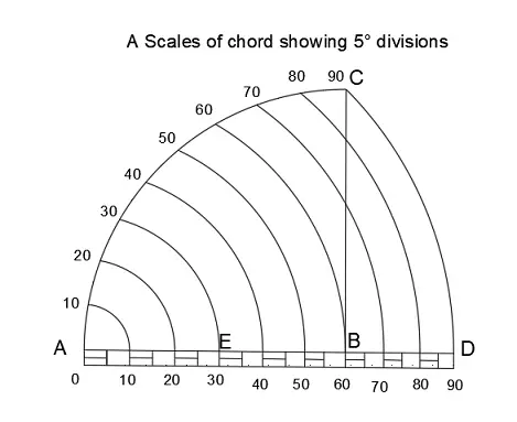
Scale of chords
In the absence of a protractor, a scale of chords may be used to measure the angle or to set the required angle. The constructions based on the lengths of chords of angles measured on the same arc.
How to Use Engineering Scales
Using engineering scales requires some practice and skill. Here are some tips to help you use engineering scales effectively:
Understand the Scale:
Before initiating the utilization of a measuring apparatus, it is imperative that one comprehends the respective units of measurement embodied within it. For instance, if the measuring tool employs inches, it is necessary to acquire knowledge on the magnitude of inches each increment embodies.
Align the Scale:
When using a triangular scale, align the scale with the edge of the paper or drawing board to ensure accuracy.
Measure Carefully:
It is highly recommended to exercise caution when utilizing a scale in order to guarantee precision and accuracy in one’s measurements. Utilizing a sharp pencil to make discernible marks on the paper is advisable, and it is crucial to measure twice to confirm the accuracy of the measurement.
Maintenance of Engineering Scales
To ensure the accuracy and longevity of your engineering scales, it’s important to maintain them properly. Here are some tips for maintaining your engineering scales:
Clean Your Scale
Regularly clean your scale with a soft cloth to remove any dirt or debris. Avoid using harsh chemicals that may damage the scale.
Store Your Scale Properly
In order to safeguard the scale’s pristine state and ensure its longevity, it is highly recommended to store the device in a protective casing or sleeve when it is not being utilized.
Check for Damage
Regularly inspect your scale for any signs of damage or wear and tear. If you notice any cracks or dents, replace the scale immediately.
Additional Information about scales in engineering drawing
The scale to be chosen for a drawing will depend upon the complexity of the object and the purpose of the representation.
In all cases, the selected scale shall be large enough to permit an easy and clear interpretation of the information depicted.
Details that are too small for complete dimensioning in the main representation shall be shown adjacent to the main representation in a separate detail view (or section) which is drawn to a large scale.
It is recommended that, for information, a full-size view be added to the large-scale representation of a small object. In this case, the full-size view may be simplified by showing the outlines of the object only.
Read Also : Types of Line in Engineering
When Should You Use Different Scales in Engineering Drawings?
Choosing the right scale depends on the size of the object and the level of detail needed. Let’s look at some examples:
1. When to Use Full Scale?
Use a full scale when dealing with small components like screws, nuts, or bolts. This ensures all details are visible and nothing is lost in translation.
2. When to Use Reduced Scale?
If you’re drawing a large object like a building or a bridge, a reduced scale is your go-to. It allows you to fit the entire structure on a single sheet while maintaining the integrity of the design.
3. When to Use Enlarged Scale?
For intricate details in small components, an enlarged scale helps you see everything clearly. This is often used in mechanical engineering for parts like gears or circuit boards.
What Are the Common Mistakes to Avoid When Using Scales?
Using scales in engineering drawings requires precision. Here are some common pitfalls to watch out for:
1. Ignoring the Scale Indicator
One of the biggest mistakes is ignoring the scale indicator. Always check it before starting any measurements. Using the wrong scale can lead to serious errors in your design.
2. Misinterpreting the Scale
Misinterpreting the scale can happen if you’re not careful. For instance, confusing a 1:10 scale with a 10:1 scale could lead to significant design flaws. Always double-check the scale before proceeding.
3. Inconsistent Scaling
Inconsistent scaling within the same drawing can cause confusion. Make sure all parts of the drawing are scaled consistently unless a specific detail requires a different scale.
4. Relying Solely on Memory
Don’t rely on memory for scale conversions. Always use a scale ruler or calculator to ensure accuracy.
What Are the Best Practices for Using Scales in Engineering Drawings?
To master the use of scales in engineering drawings, follow these best practices:
1. Double-Check Your Scale
Before finalizing any drawing, double-check the scale to ensure it matches the intended design. This simple step can prevent costly errors down the line.
2. Use Scale Rulers
Invest in a good set of scale rulers. They make measuring and converting scales much easier and more accurate.
3. Label Your Drawings Clearly
Always label the scale on your drawings clearly. This helps others understand your work without confusion and reduces the risk of misinterpretation.
4. Stick to Standard Scales
Whenever possible, stick to standard scales like 1:10, 1:50, or 1:100. These are widely recognized and make collaboration easier.
5. Practice Regularly
Like any skill, using scales in engineering drawings gets easier with practice. Regularly working with different scales will help you become more comfortable and efficient.
Do You Know?
Did you know that the concept of scale has been around since ancient times? Early engineers and architects used basic scaling techniques to create accurate representations of structures like the pyramids and Roman aqueducts. Without scales, many of the world’s greatest architectural achievements wouldn’t have been possible!
Key Takeaways
- Scales in engineering drawings are crucial for accurately representing real-world objects on paper.
- Different types of scales serve different purposes, from full scales for small objects to reduced scales for large structures.
- Reading and using scales requires precision and practice, but following best practices can make the process much easier.
- Common mistakes like misinterpreting the scale or ignoring the scale indicator can lead to serious design flaws.
- Investing in tools like scale rulers and regularly practicing can help you master the art of using scales in engineering drawings.
Conclusion
Understanding scales in engineering drawings is essential for anyone involved in design and construction. Whether you’re working on a skyscraper or a tiny component, the scale ensures your drawings are accurate and easy to interpret. By following the best practices and avoiding common mistakes, you’ll be well on your way to mastering this critical skill.
FAQs:
What is scale in civil engineering?
In civil engineering, “scale” refers to the ratio between a linear dimension of a physical object and the corresponding dimension on a representation or drawing of that object. It’s a fundamental concept used in the design, planning, and visualization of various civil engineering projects, including buildings, bridges, roads, and infrastructure.
What is a full scale in engineering drawings?
In engineering drawings, a full-size scale means that the drawing is scaled to the actual dimensions of the thing represented.This means that the dimensions on the design accurately represent the dimensions of the object.
What is a 2:1 scale drawing?
A 2:1 scale drawing is also known as a half-scale drawing. In a 2:1 scale drawing, every dimension is exactly half of their actual size.
A component of 100 mm of actual length, and would be drawn as 50 mm in length on a half-scale drawing.
What is a reduction factor or reduction ratio in engineering drawings?
A reduction factor (RF), additionally known as a reduction ratio, is a numerical value that indicates how the dimension of an object on an engineering design relates with its actual dimensions in the real world. It is frequently written as a ratio or fraction.
What is an isometric scale?
Drawing accurate isometric projections is usually done using an isometric scale. All distances in this scale are 2/3 of actual size, or around 80% of actual size.
What is plain scale?
Plain scale, also known as a linear scale or bar scale, is a simple graphical representation of measurements typically depicted as a straight line divided into equal segments. Each segment represents a specific unit of measurement, such as meters, feet, or kilometers. The plain scale is straightforward to use and is commonly found on maps, architectural drawings, and engineering plans.
What is diagonal scale?
Diagonal scale, also known as a graduated scale, is a specialized type of scale used to represent measurements in a non-linear or logarithmic manner. Unlike a plain scale, which uses a straight line, a diagonal scale employs a series of diagonal lines or segments to represent measurements. Diagonal scales are commonly used in engineering and scientific drawings where precise logarithmic scaling is necessary, such as in electrical engineering diagrams or logarithmic graphs.
